v2 Build Log
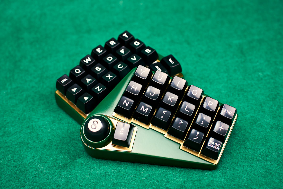
I’ve been using my Oddball v1 for around 6 months. I really like it; having a trackball embedded in the keyboard really exceeded my expectations. It helps with all kinds of everyday tasks, and saves you from blindly having to find your way to your mouse and back again. I was actually finding it a bit limiting when switching back to a more traditional keyboard with a separate mouse; so much so I decided to build another so I could have one for both work and at home. However, if I was going to make another, there were some improvements I wanted to make!
Improving the trackball
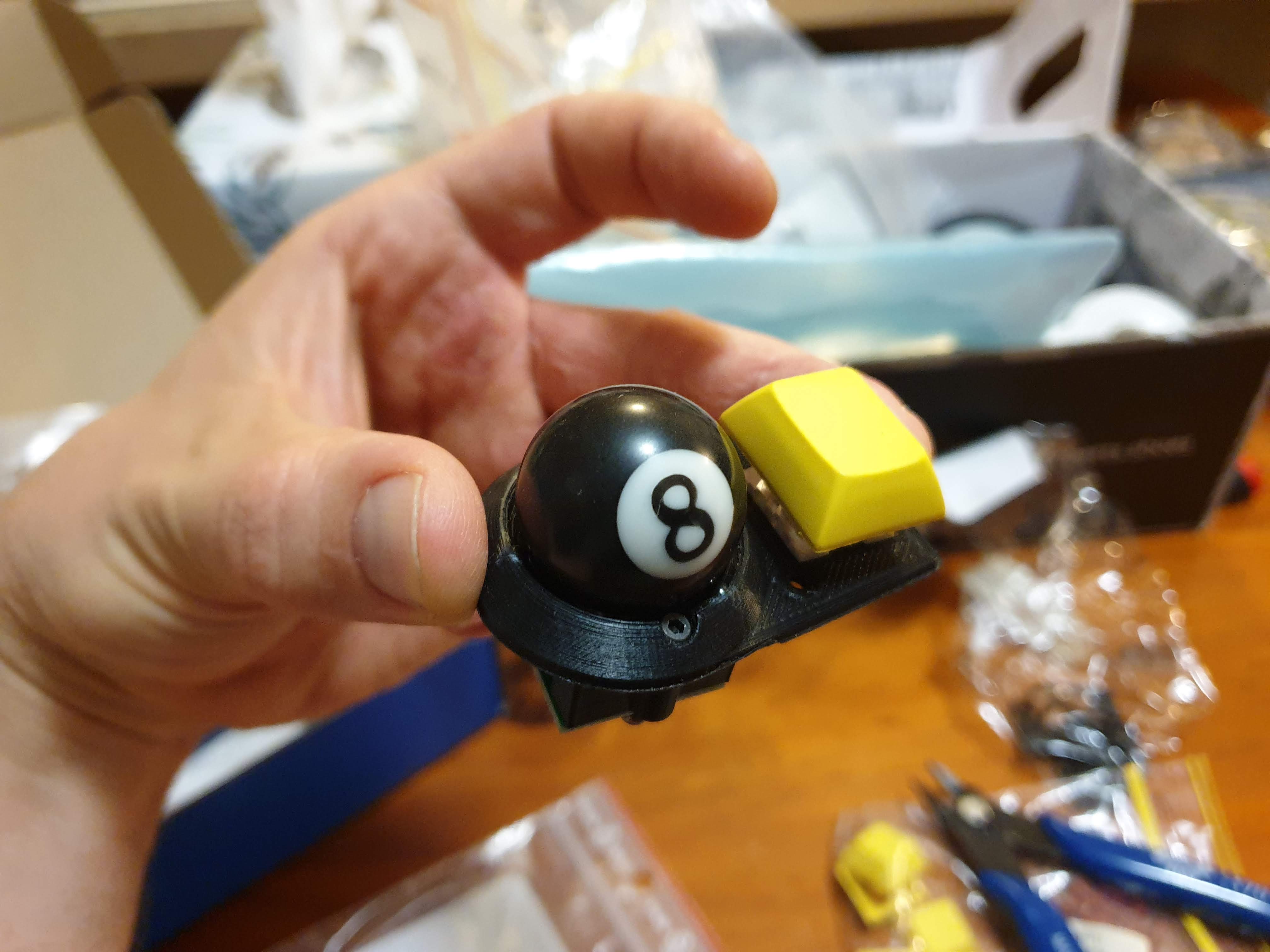
Position
The trackball was a tiny bit of a stretch. While not a dealbreaker, I wanted it a little lower and closer to the thumb.
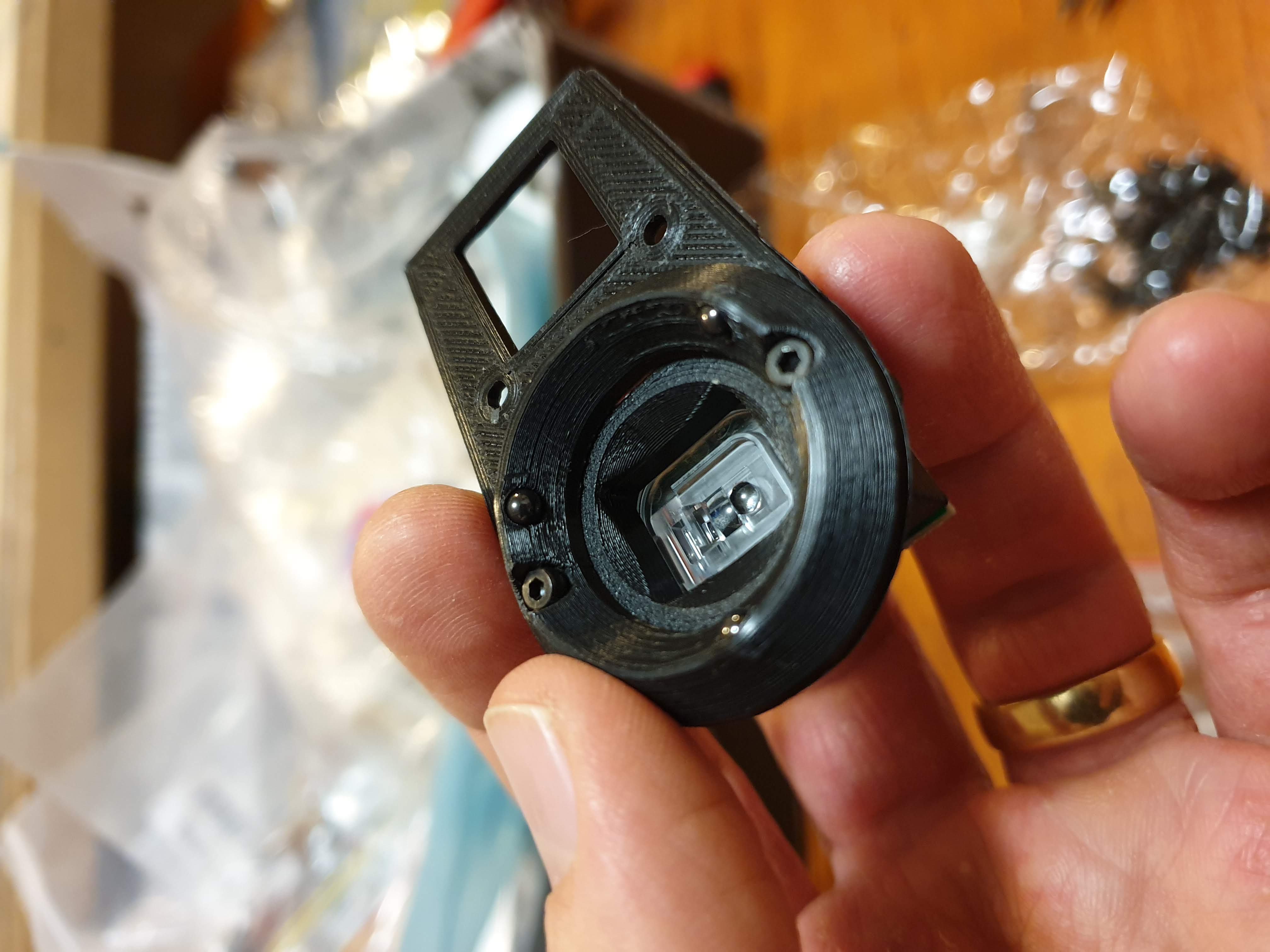
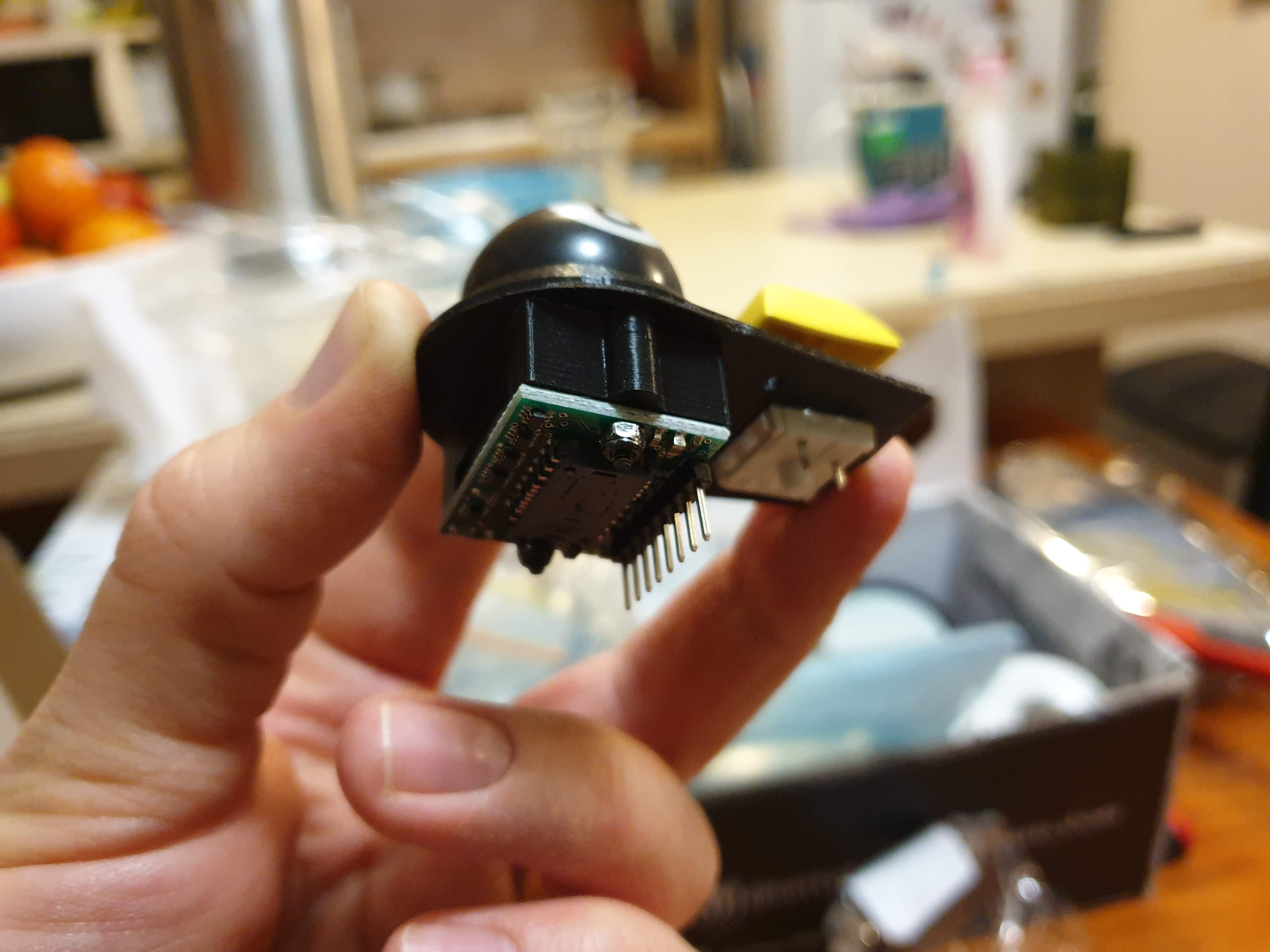
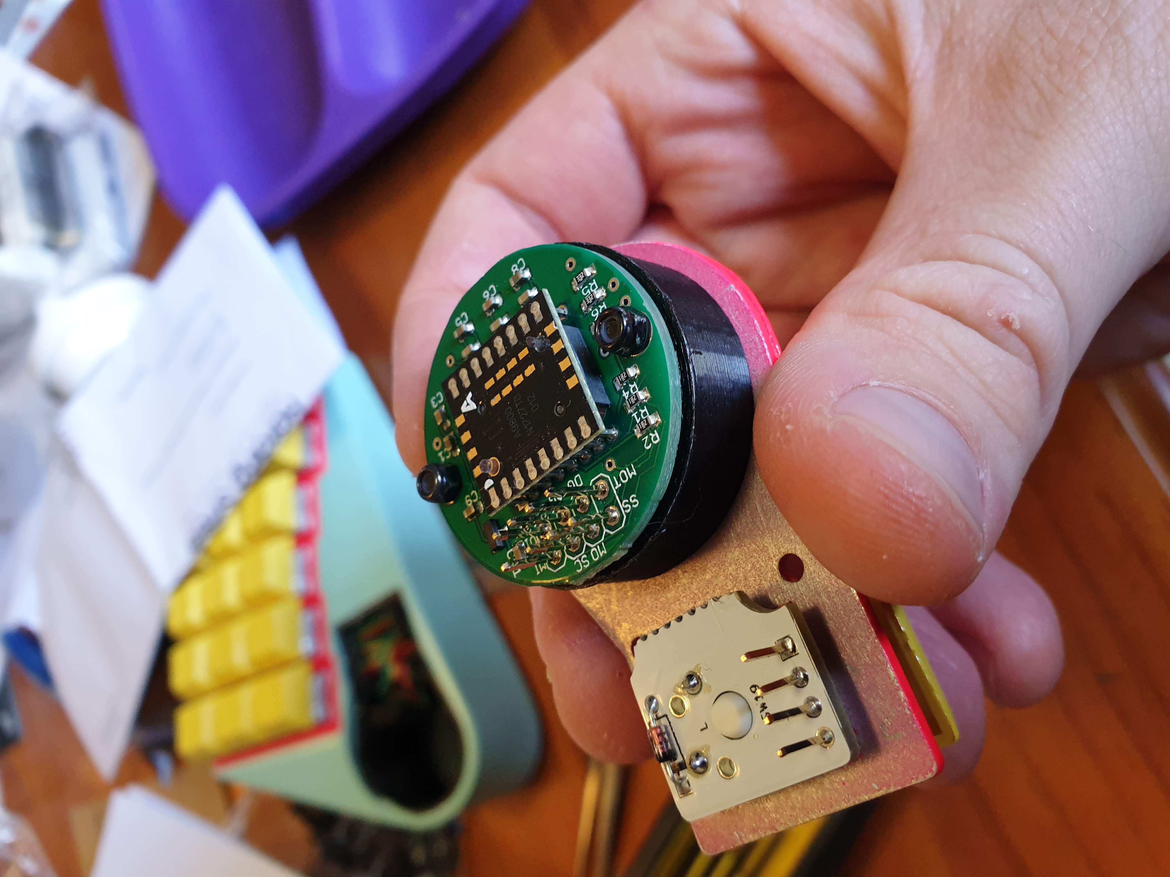
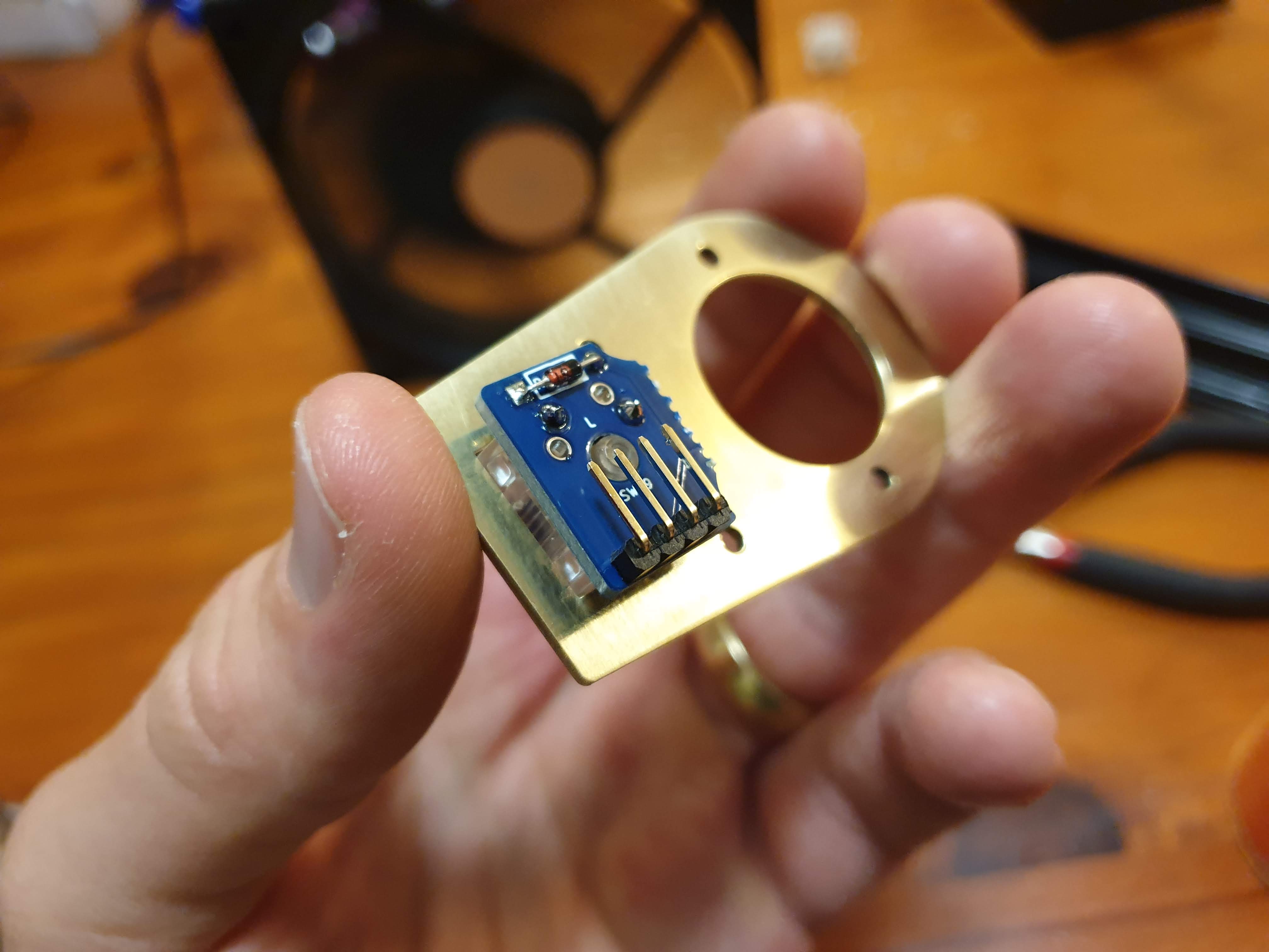
Sensor and mount
The ADNS9800 sensor was fine, but I’d noticed the Ploopy trackball was using the PMW33600 internally, which was slightly newer, offered higher CPI, ran with more flexible input voltages, along with a few other features. The PMW3360 was a slightly newer sensor, and although seeemed to be manufactured by different companies, the interfacing code needed was nearly identical, so it was pretty easy to switch. Again, JACK Enterprise on Tindie had a breakout board with the necessary resistors/capacitors/etc ready to go.
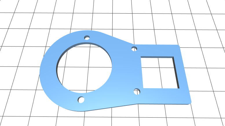
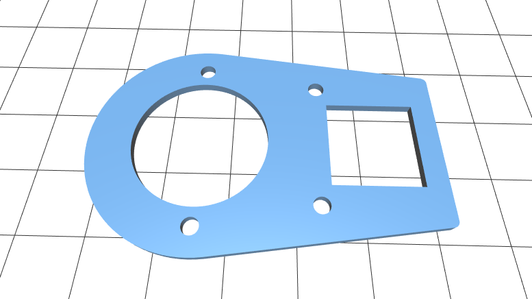
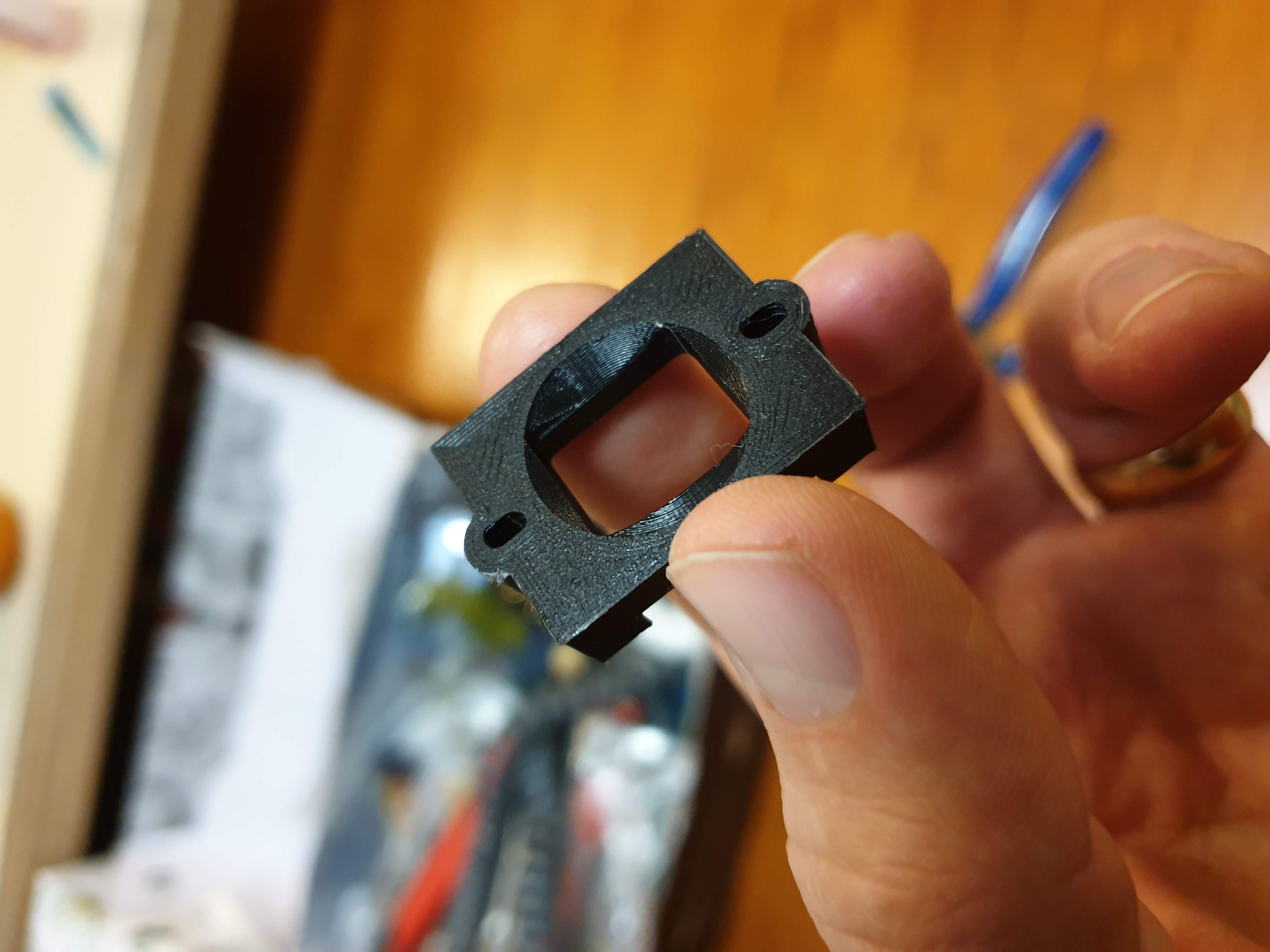
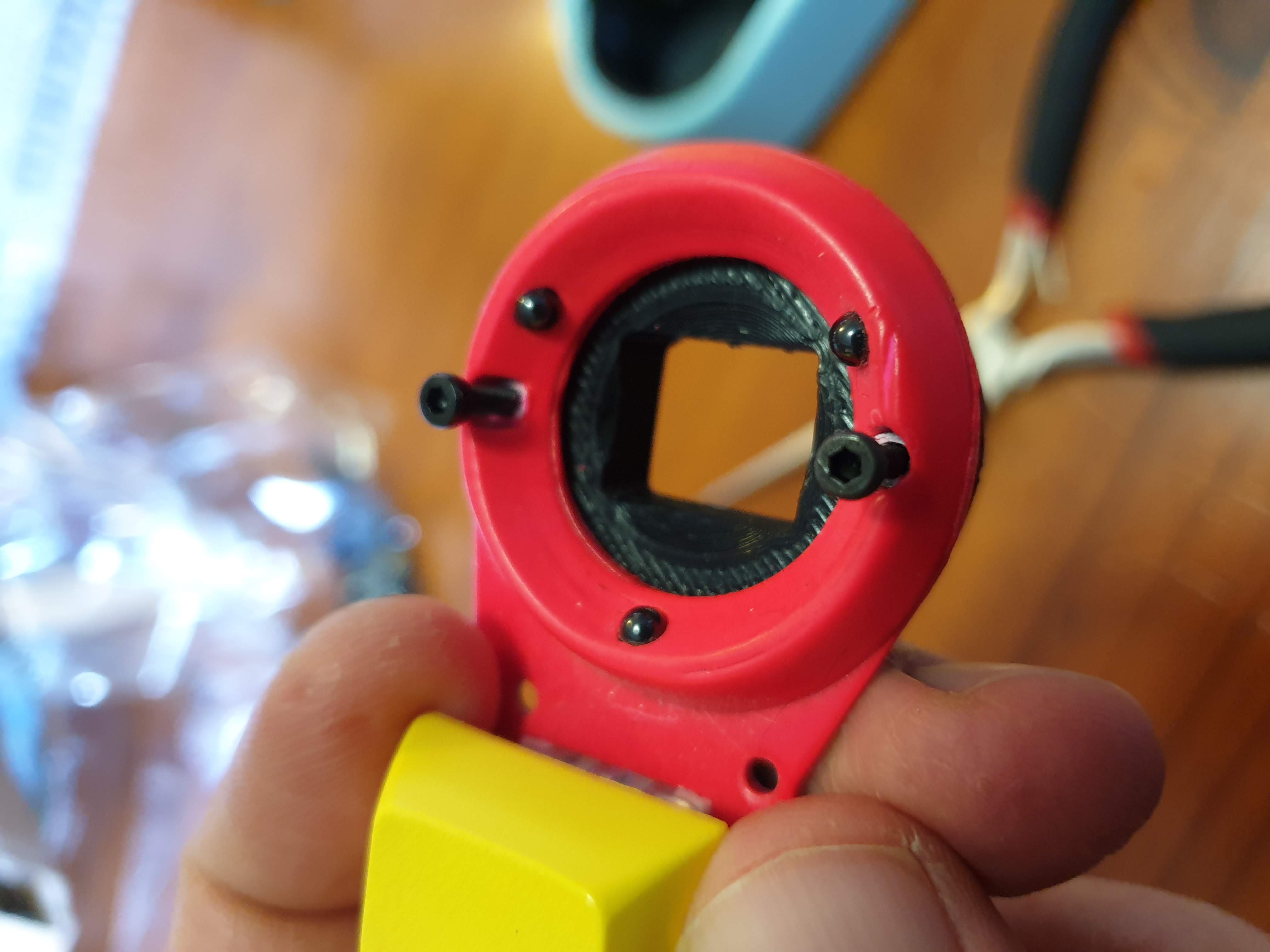
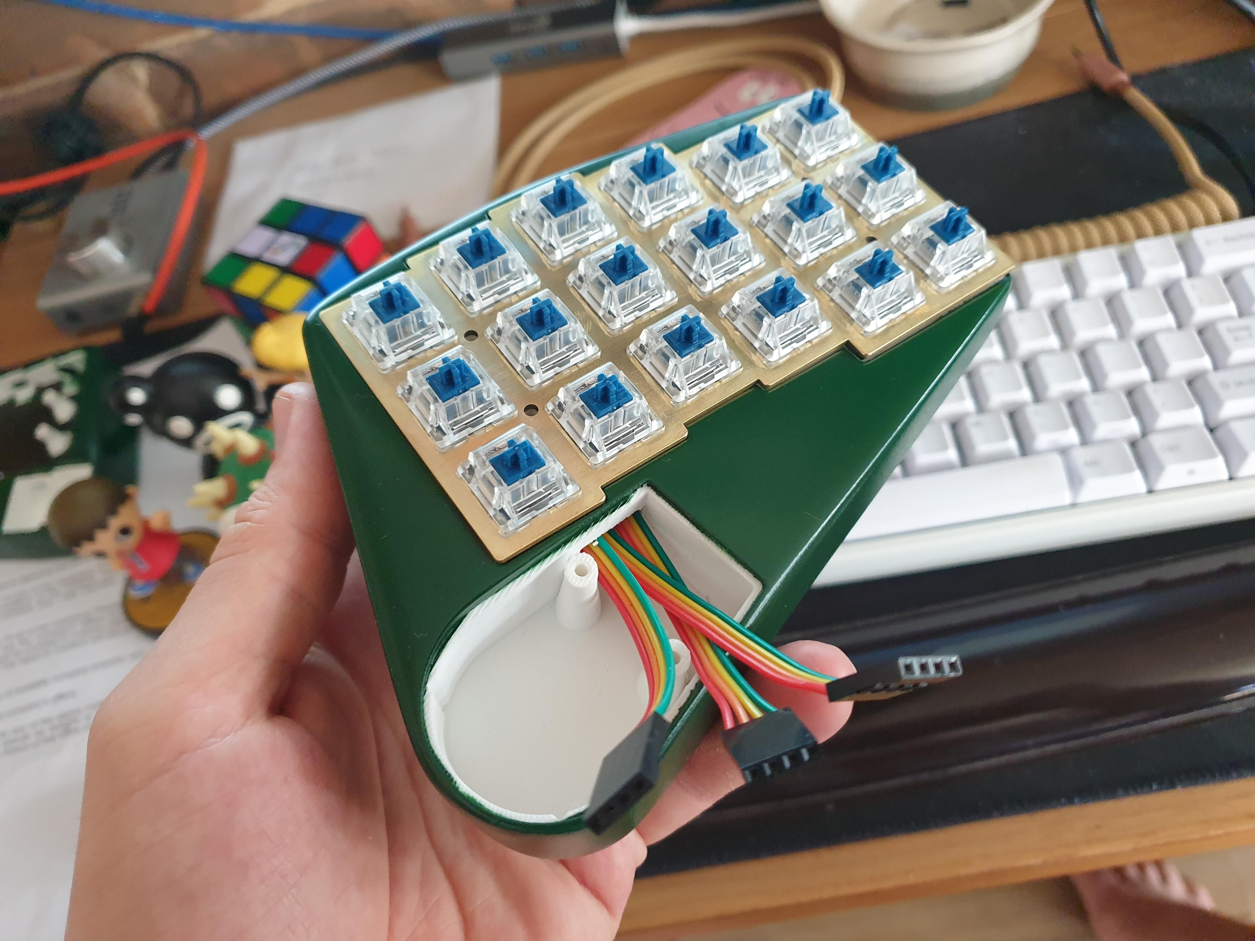
It was a slightly different shape, so it forced me to increase the plate and housing a little around the trackball. I printed a cover to fit it nicely, rather than relying on M2 standoffs, as previously the lens could fall out if you jiggled the whole assembly upsidedown.
As a bonus, going over the trackball code for v1 for the PMW changes, I found a few bugs and improved the trackball motion for v1!
I also went back and added a similar cover for the ADNS9800, which I’d used in v1, but also wanted to support in v2:
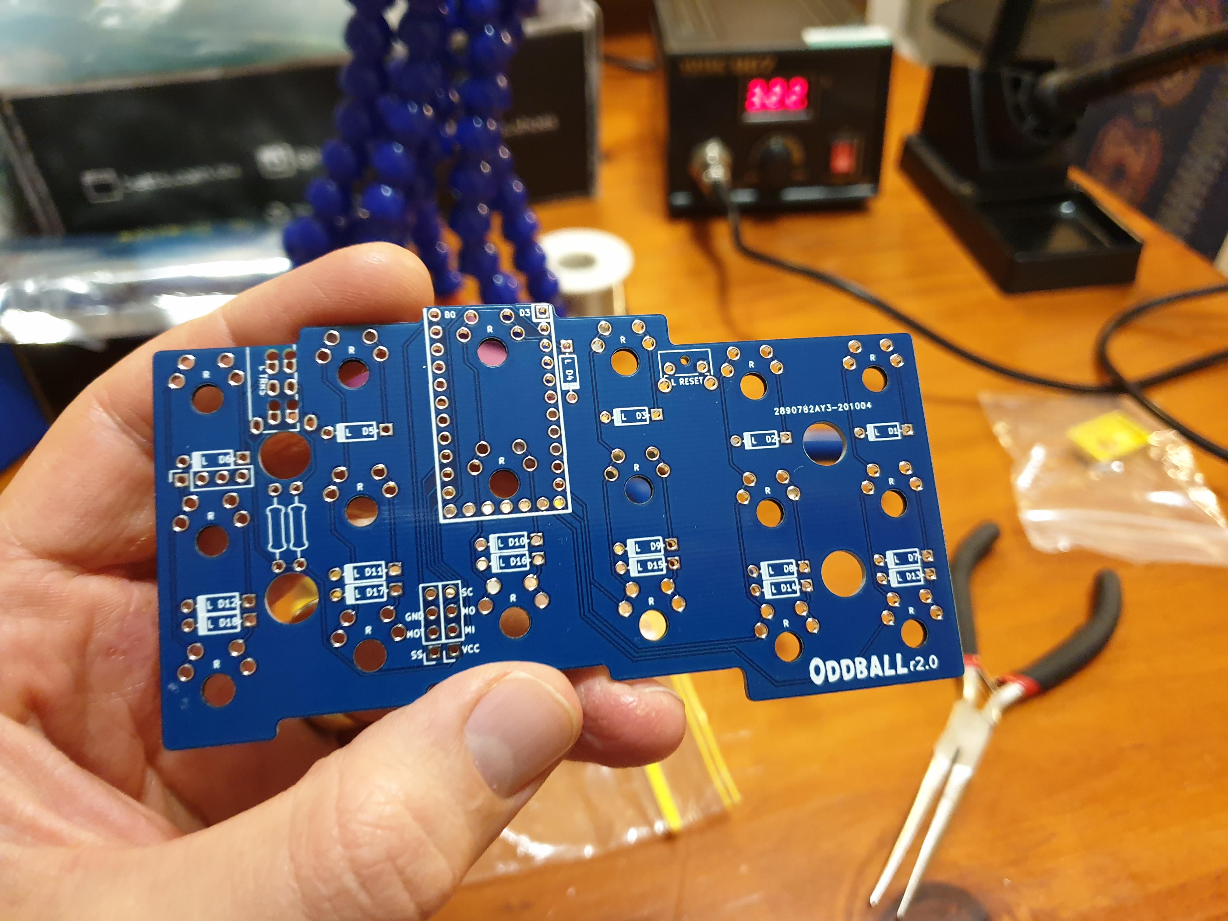
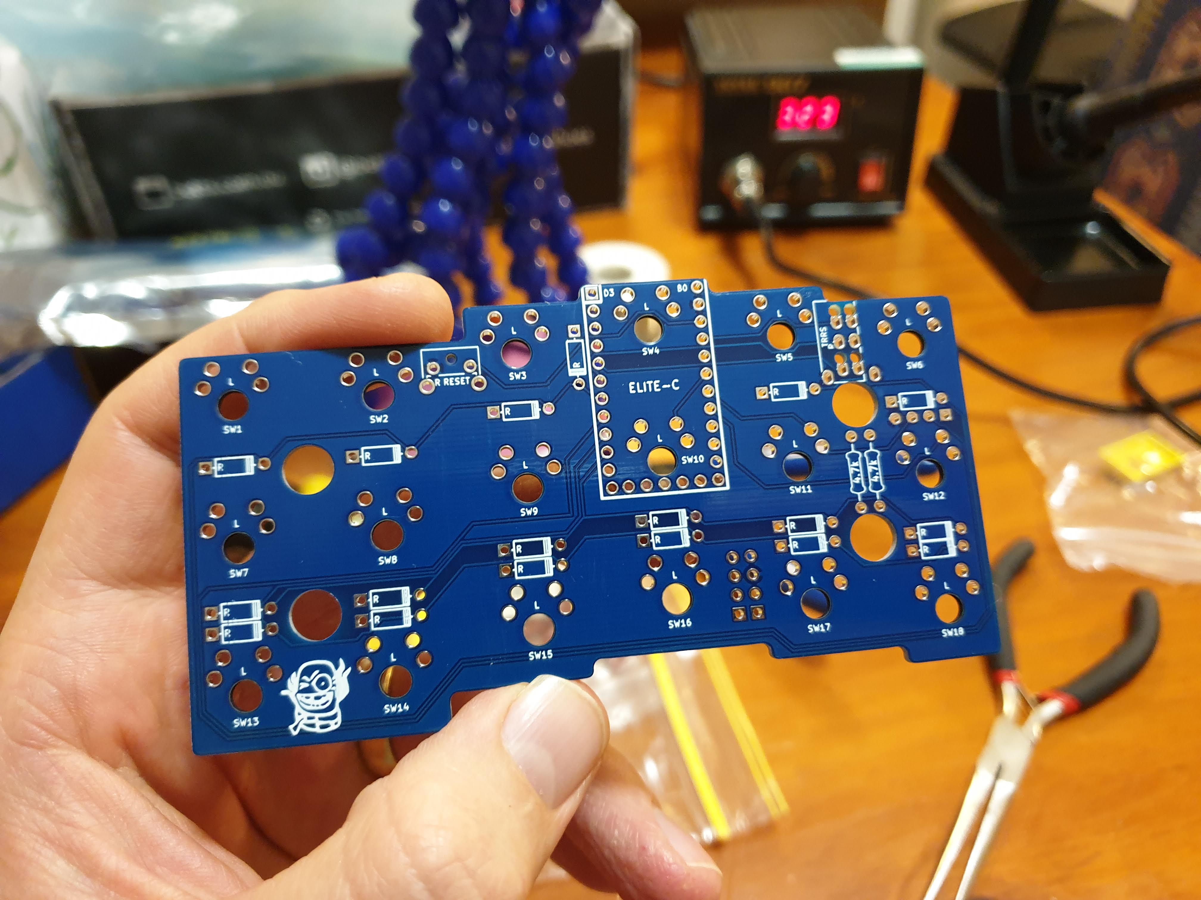
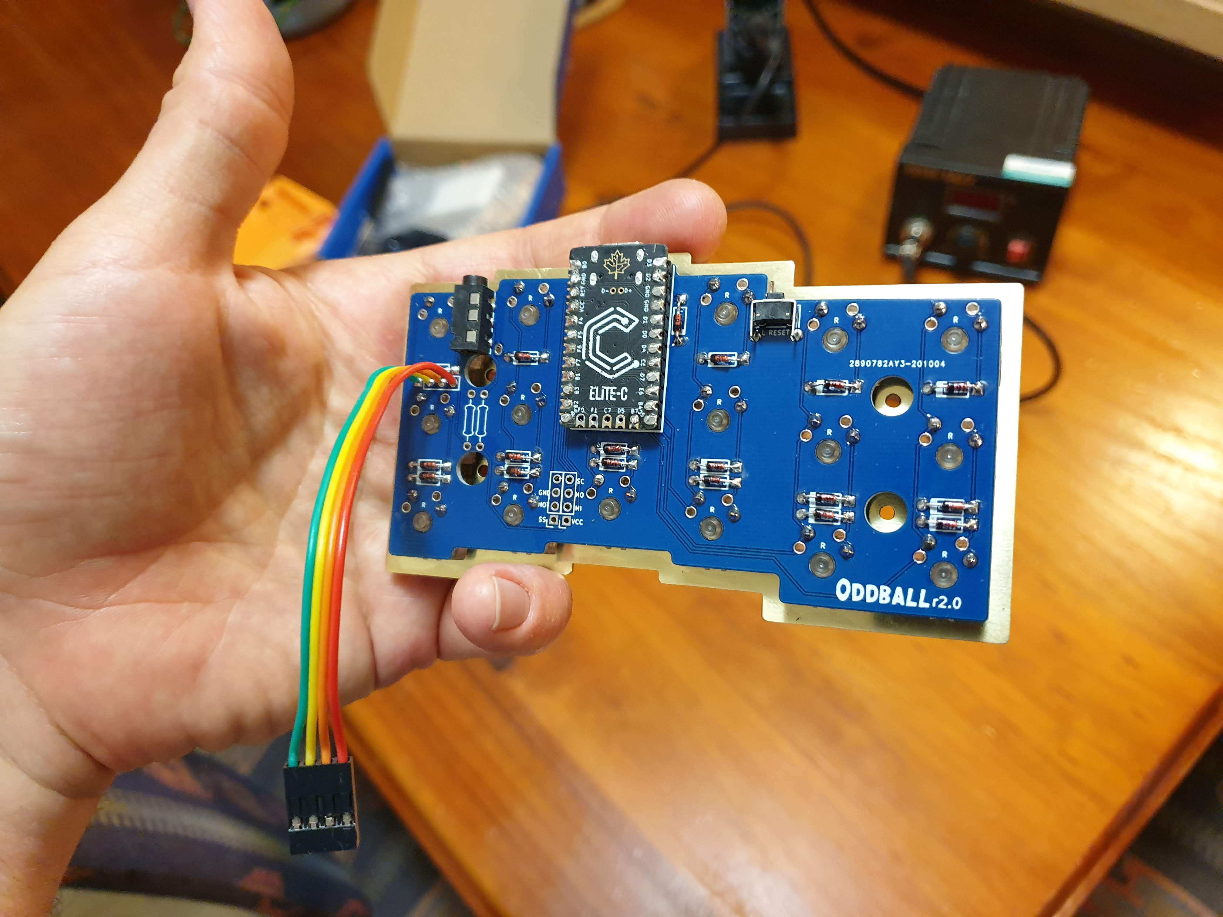
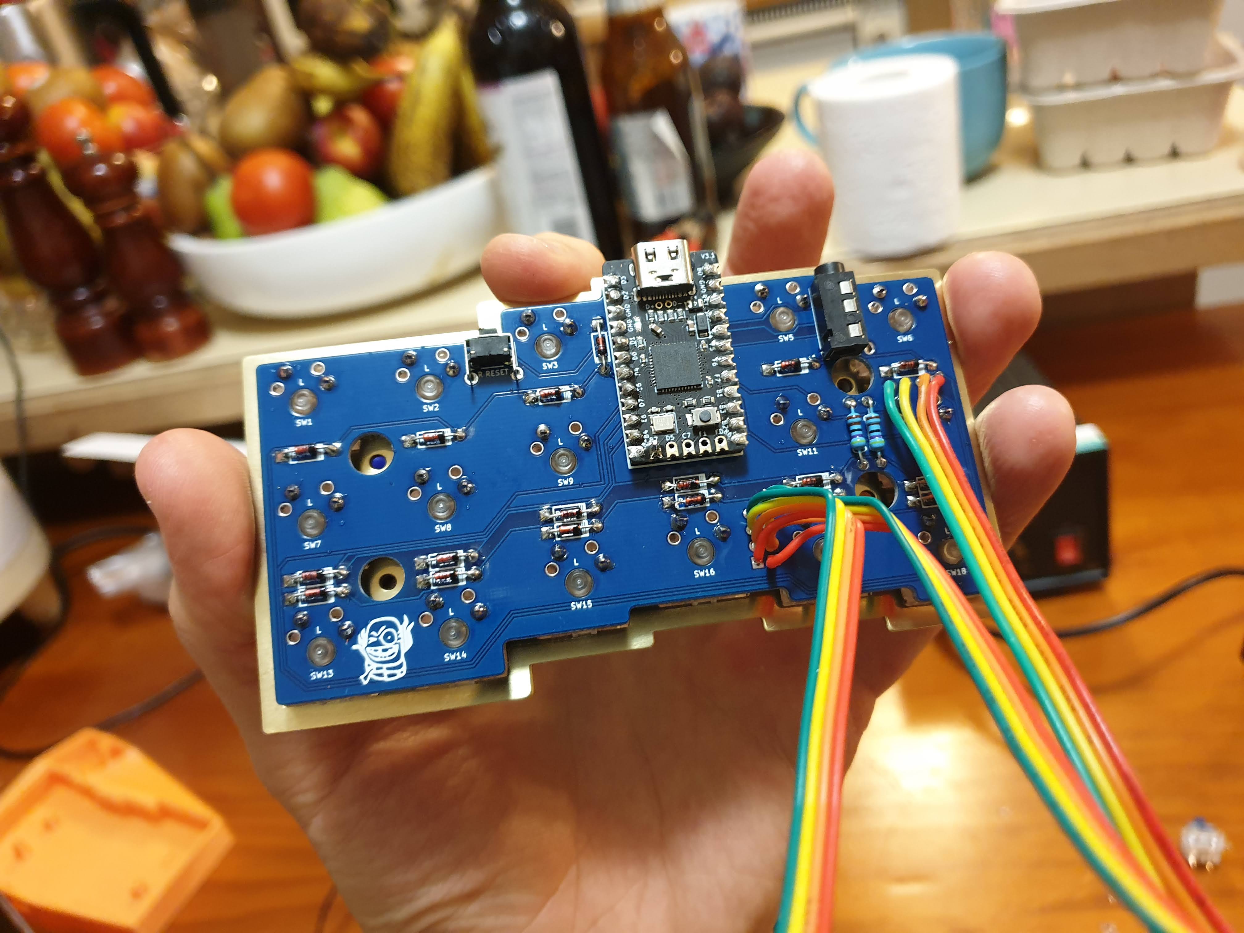
Improving the PCB
Oddball v1 had included my first PCB design, and in it I’d made a few mistakes. The main issues were a few silkscreens were back-to-font (diodes and TRRS sockets), and not enough clearance between the TRRS jacks and the switches. These were relatively easy fixes, which I ammended in the r1.1 PCB, and doubled checked for r2.0 PCB; and apparently double checking isn’t quite enough, as there is now a r2.1 PCB.
I’d used Teensy 2.0 MCUs in v1, which used Micro USB ports, which are slightly dated. USB-C is much more convenient, especially when you are plugging a cable into a socket behind a keyboard you can’t really see. As another bonus, the pinout is similar to Pro Micros or something like the nice!nano if I/someone ever wanted to make the Oddball wireless.
Improving the code
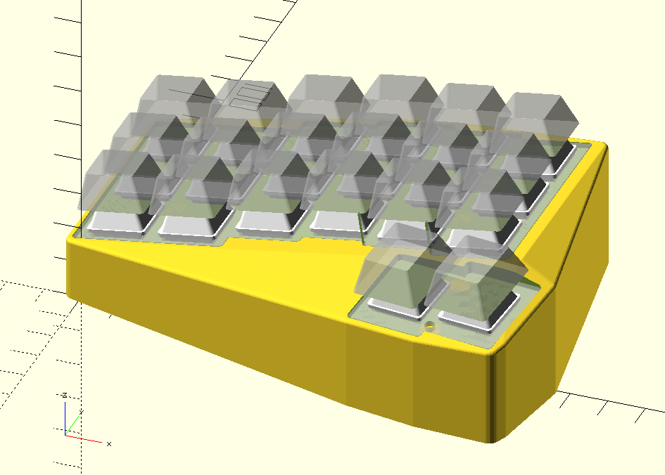
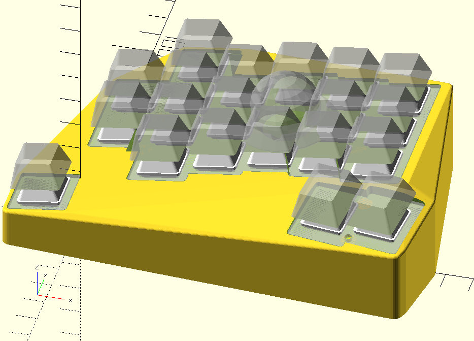
Case
I doubt many people will care, but I completely rewrote the OpenSCAD code for v2. I even nearly managed to do it all with barely any magic numbers, but a few snuck in. The rewrite should make it much easier for me if I (or perhaps someone else) ever come back to this code base and needs to change something.
QMK
As I mentioned earlier, in adding suport for the PMW3600, I also came across some bugs in my initial code which I’ve now fixed:
- failed debounces (keys occasionally registered multiple times)
- mouse jittering
- keyboard failing to start
Assembly
If you’d like to see a step-by-step guide, rather than the outcome at various stages, you can jump over to the build guide.
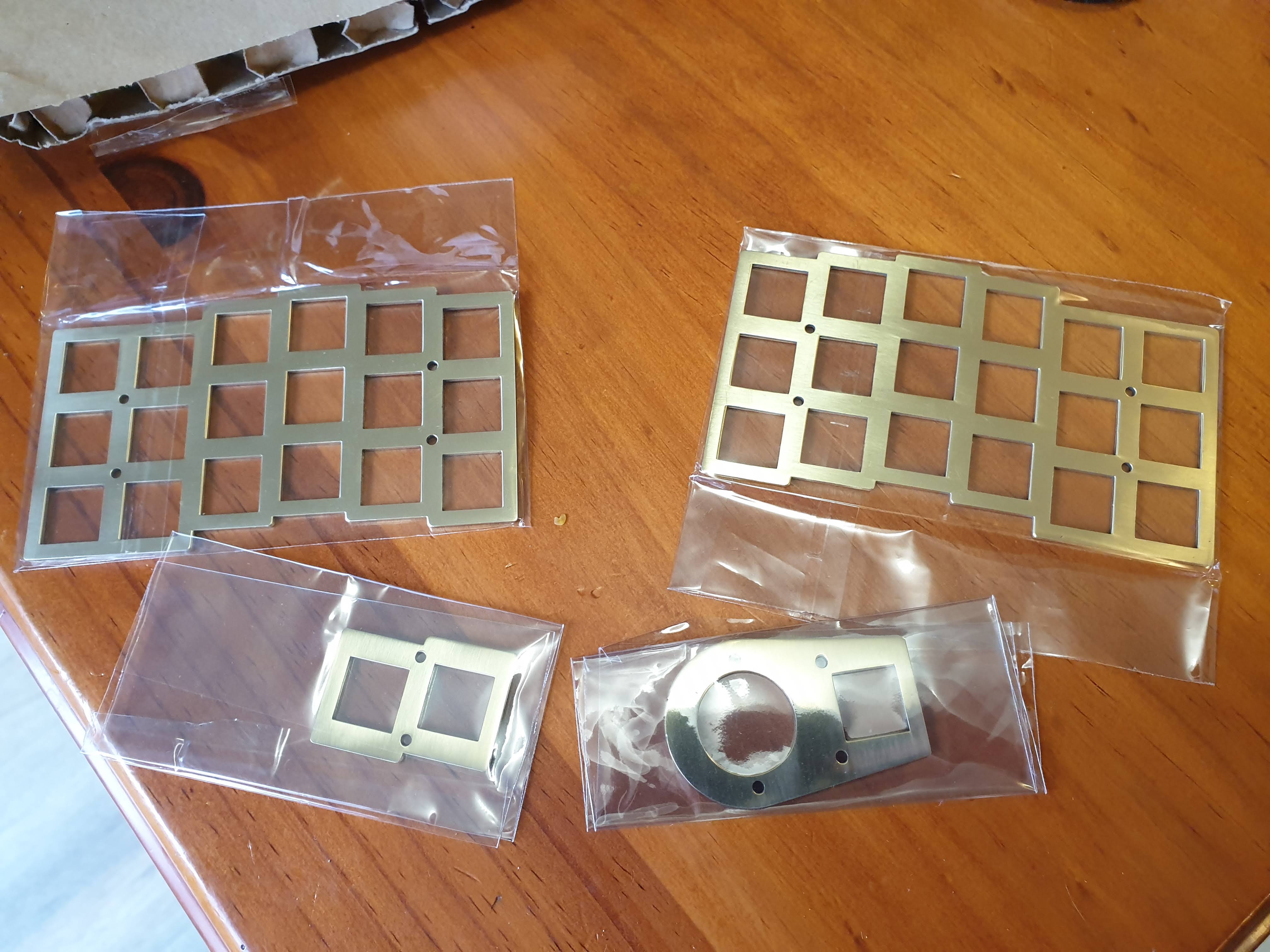
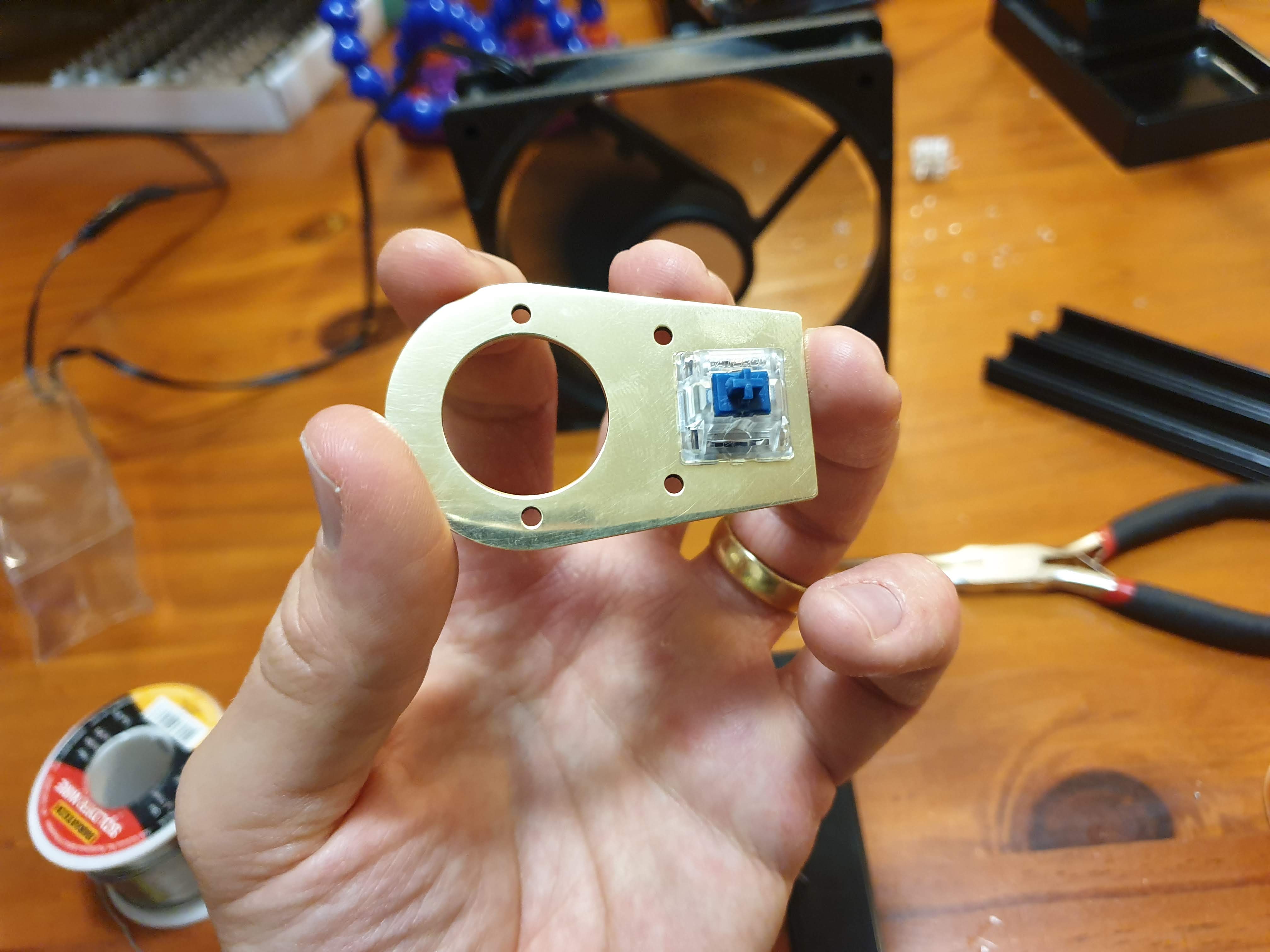
Plates
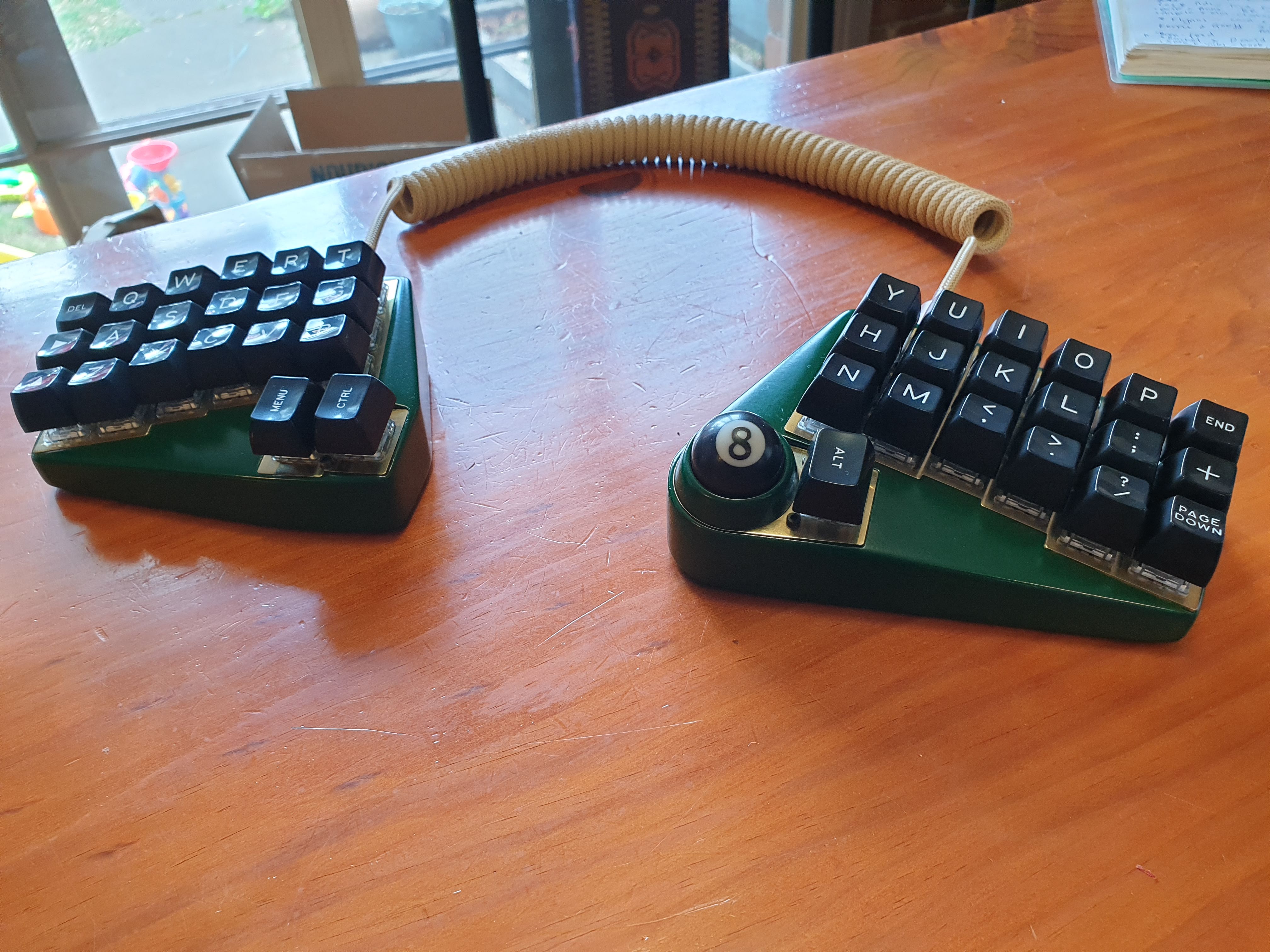
The kids-toy-vibe of the v1 was cute, but I thought I’d try to go a bit more stylish for v2. This involved not painting the plates, and getting brass plates instead.
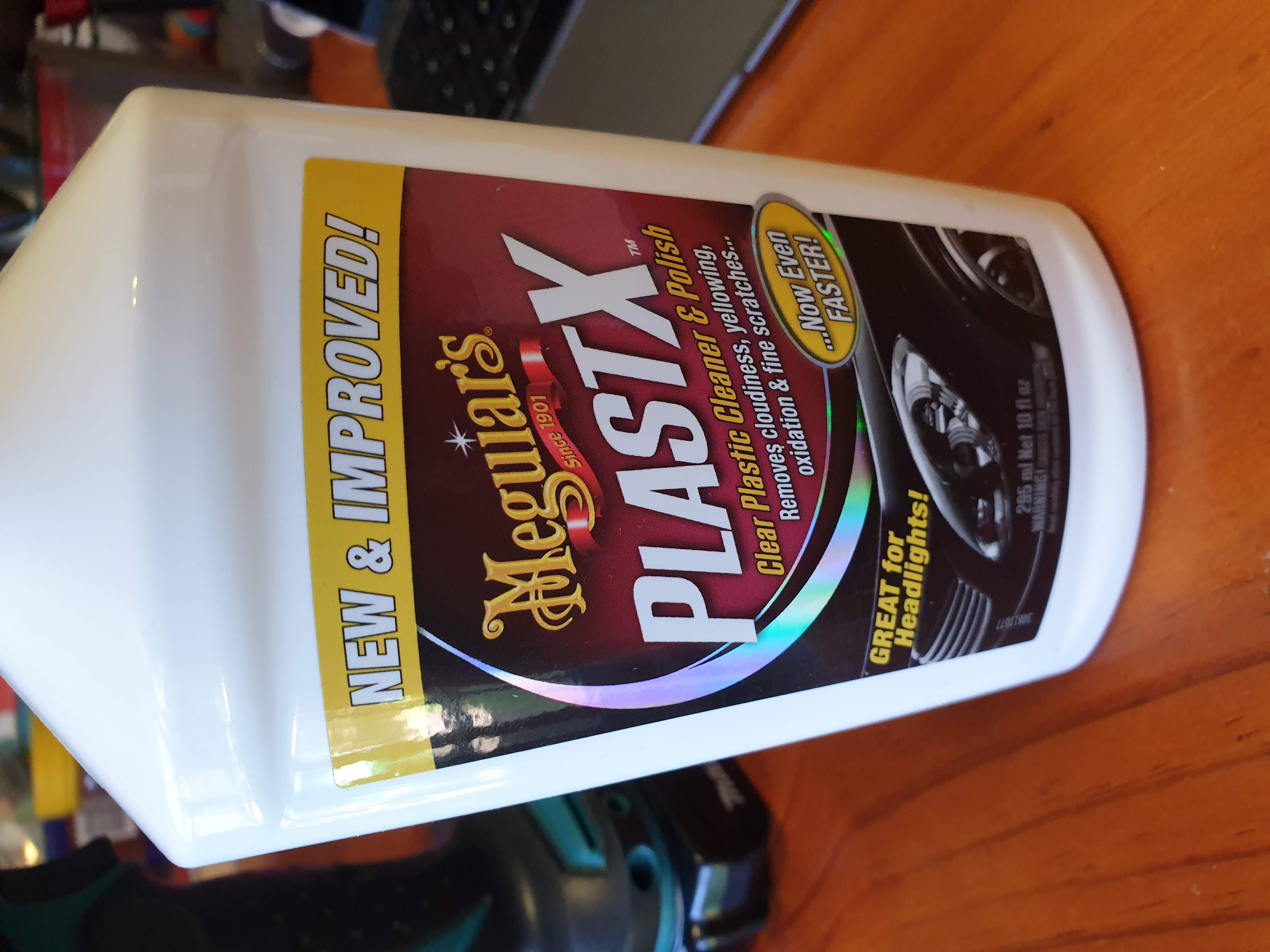
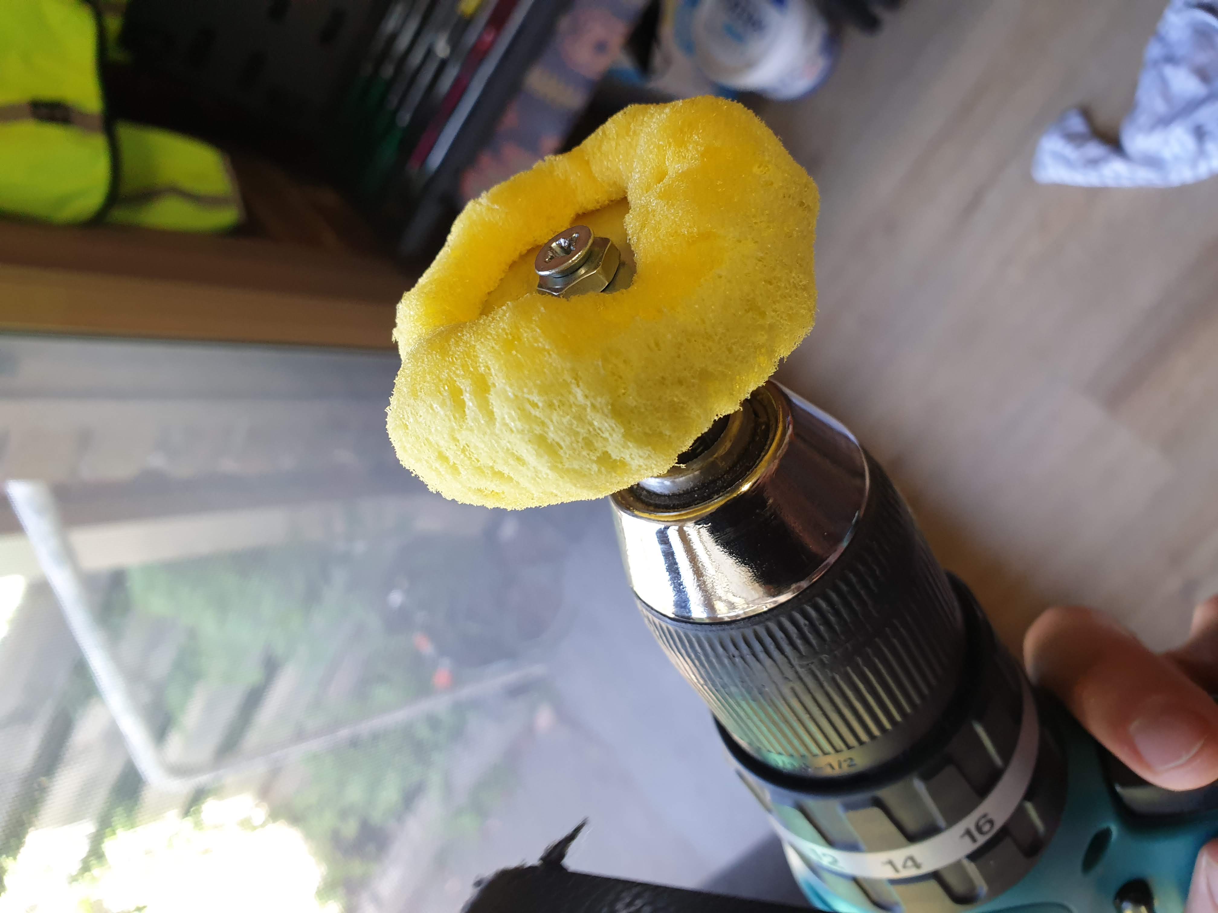
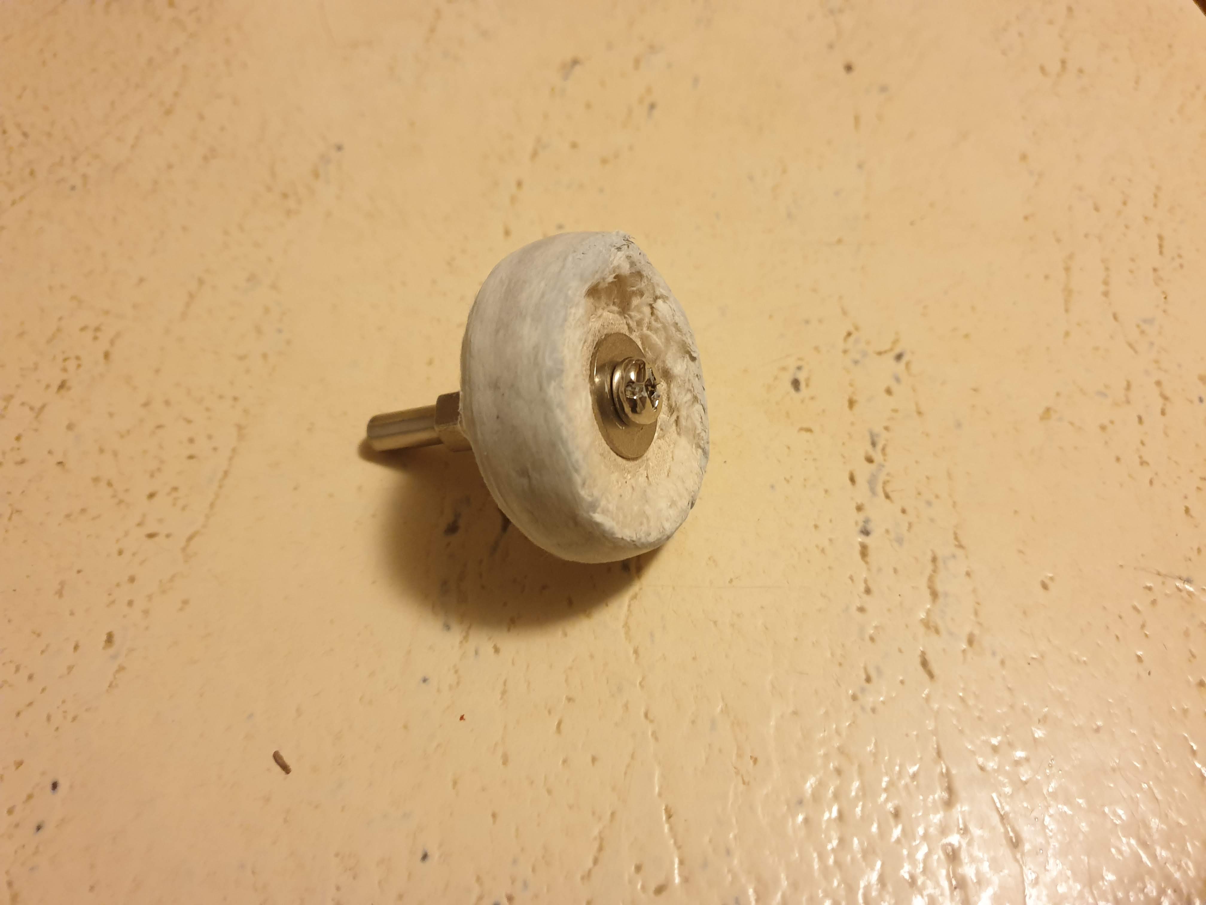
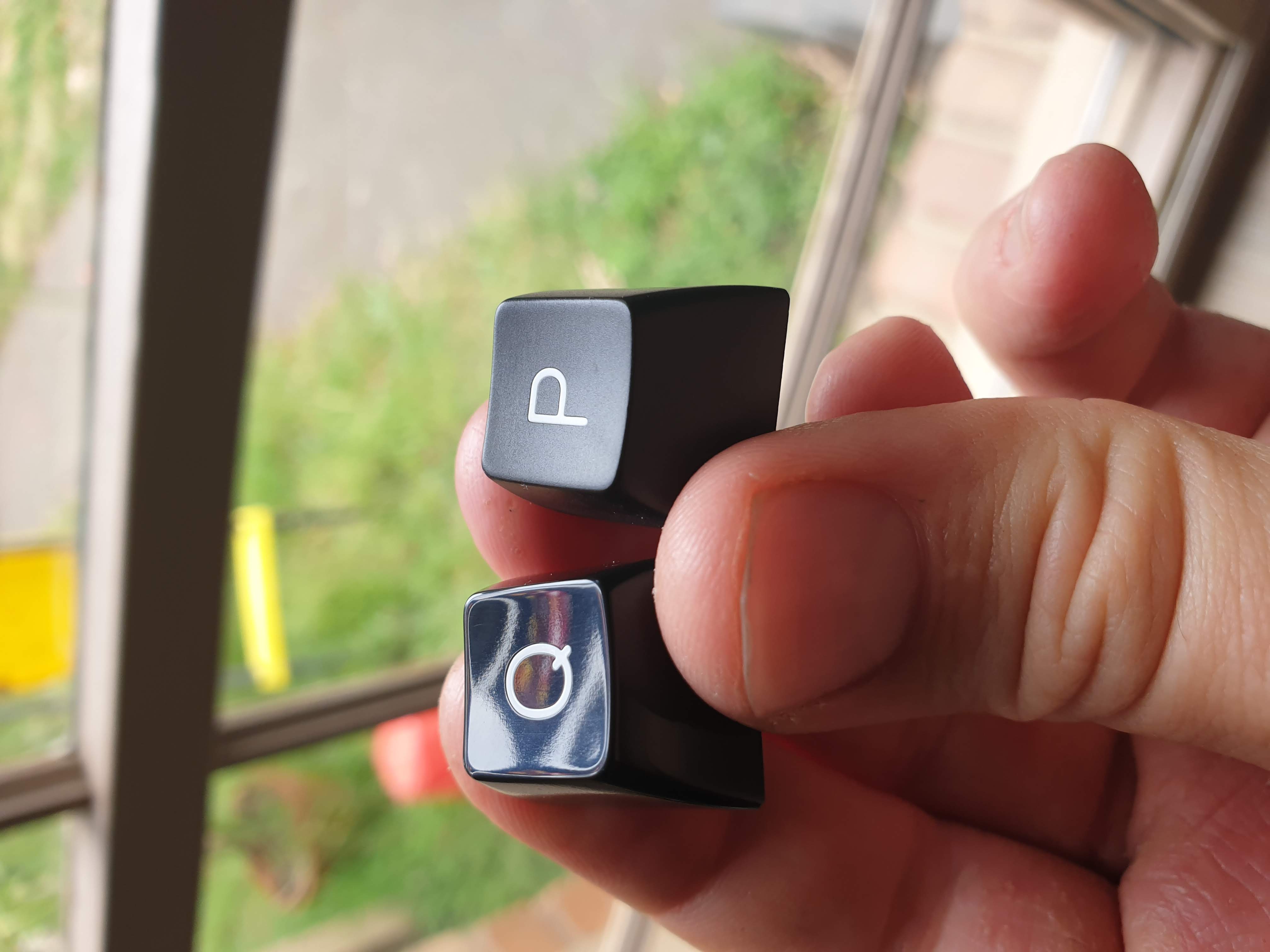
Keycaps
I wanted to go for a more retro, utilitarian look, so I thought SA keycaps fit the bill. I also though shiny keycaps looks more retro, so I decided to polish them. This took ages! Around five minutes per key; lucky I only had to do 39 and not a full size keyboard. (I’ve since learnt that one can use acetone to shine ABS more quickly and to a higher degree).
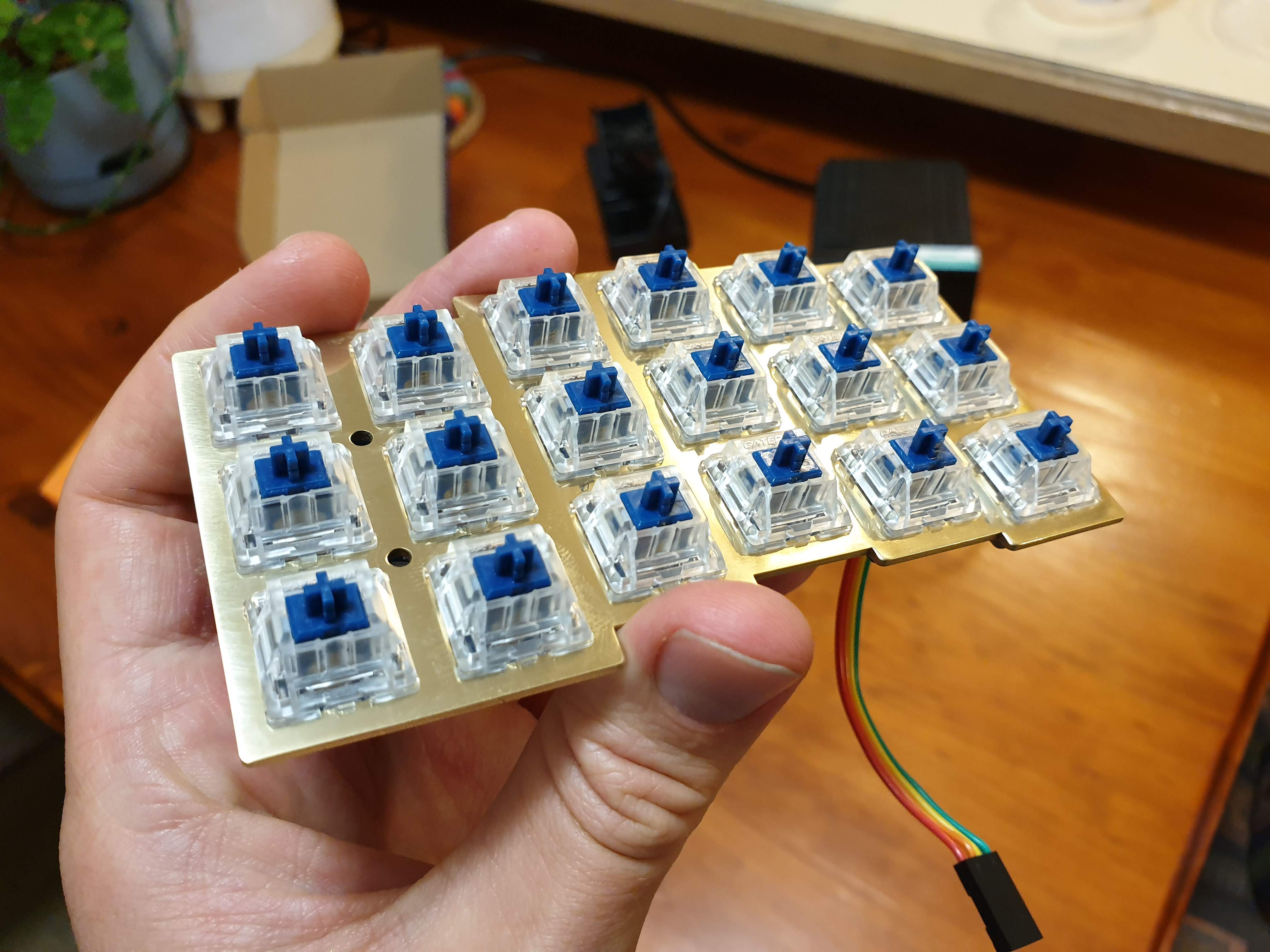
Plates and PCBs
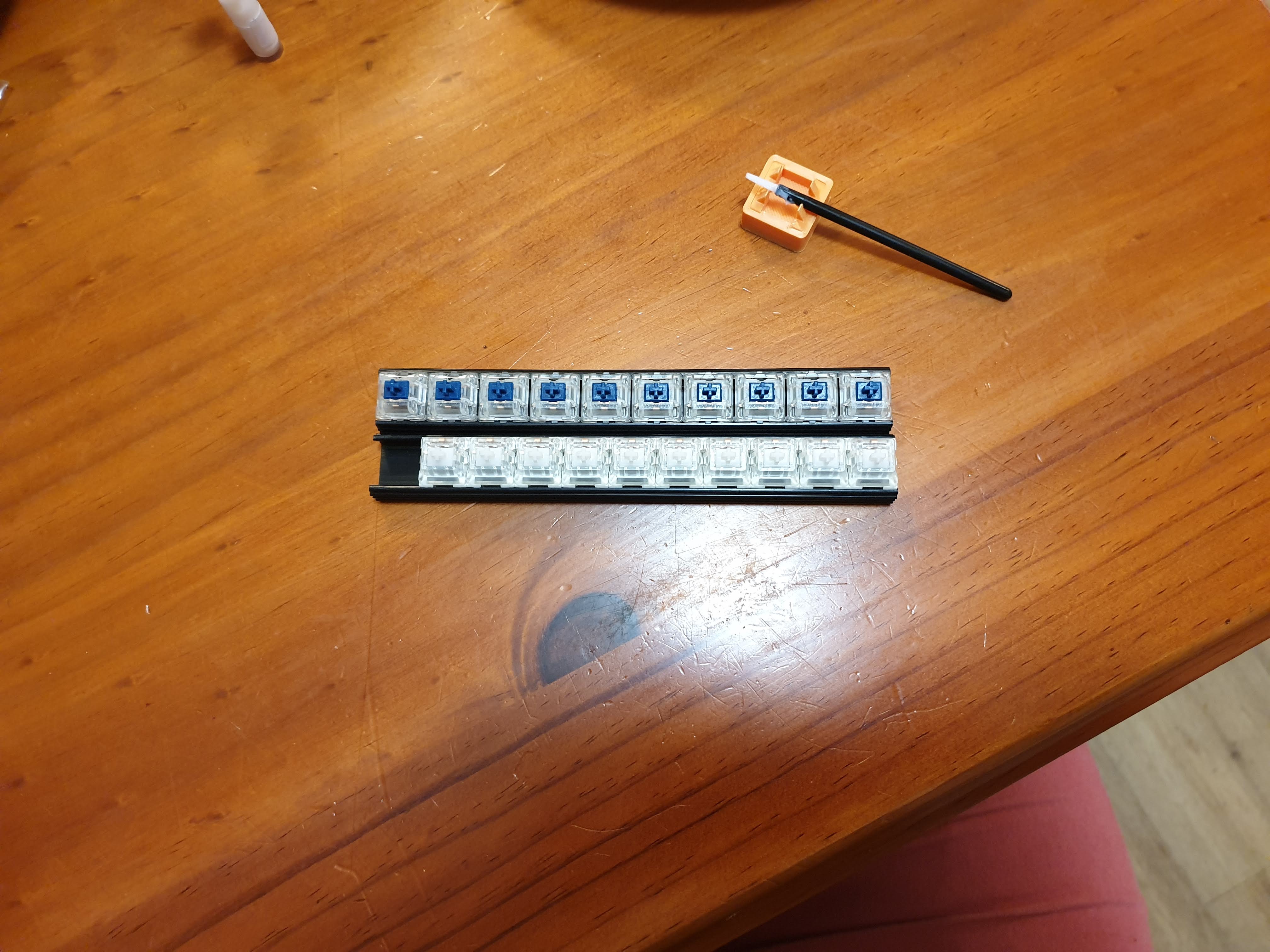
Switches
This was the first build where I lubed the switches. I used 67g Zilents, lubed with Tribosys 3204, and GPL 107 oil for the springs.
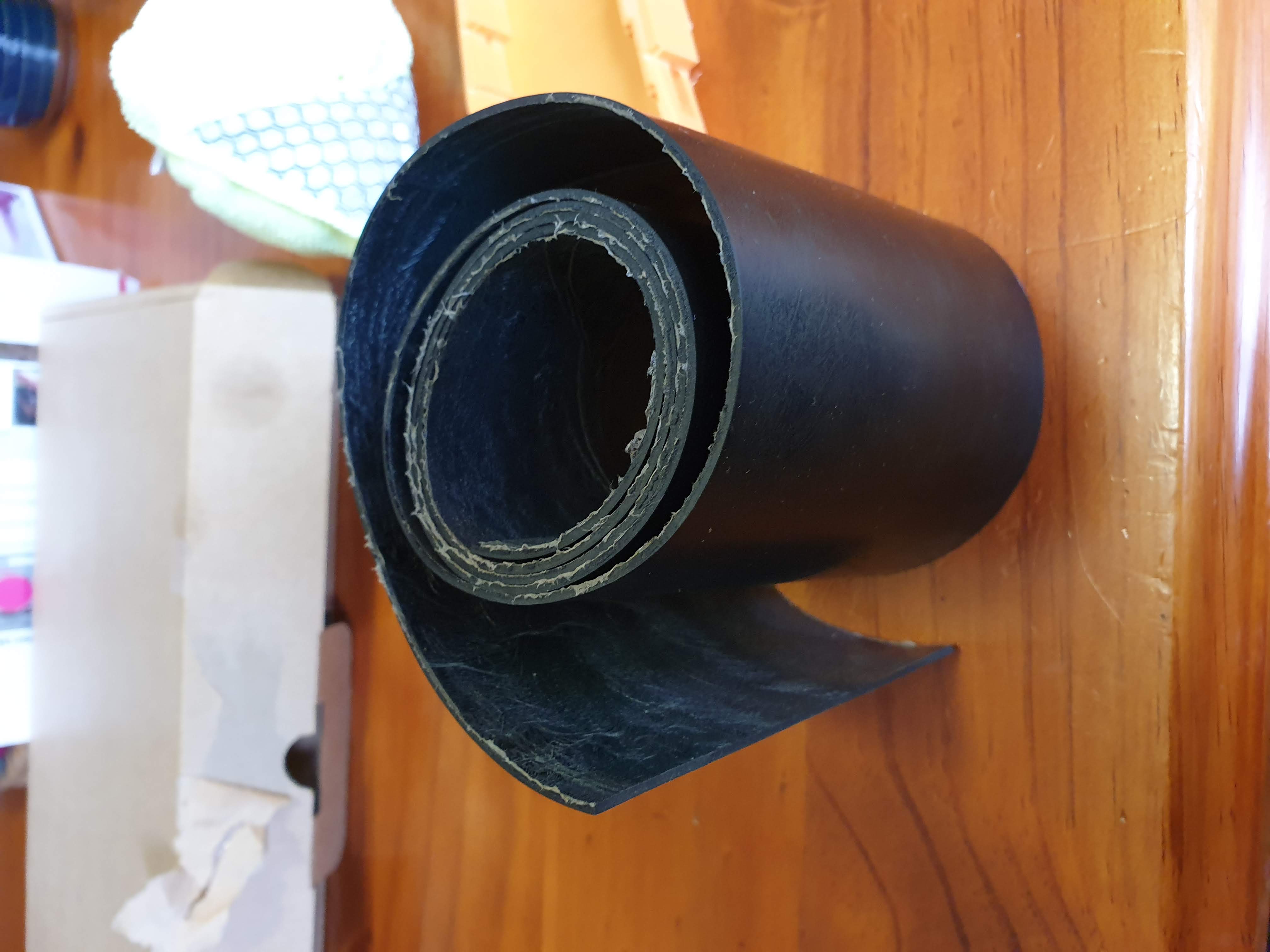
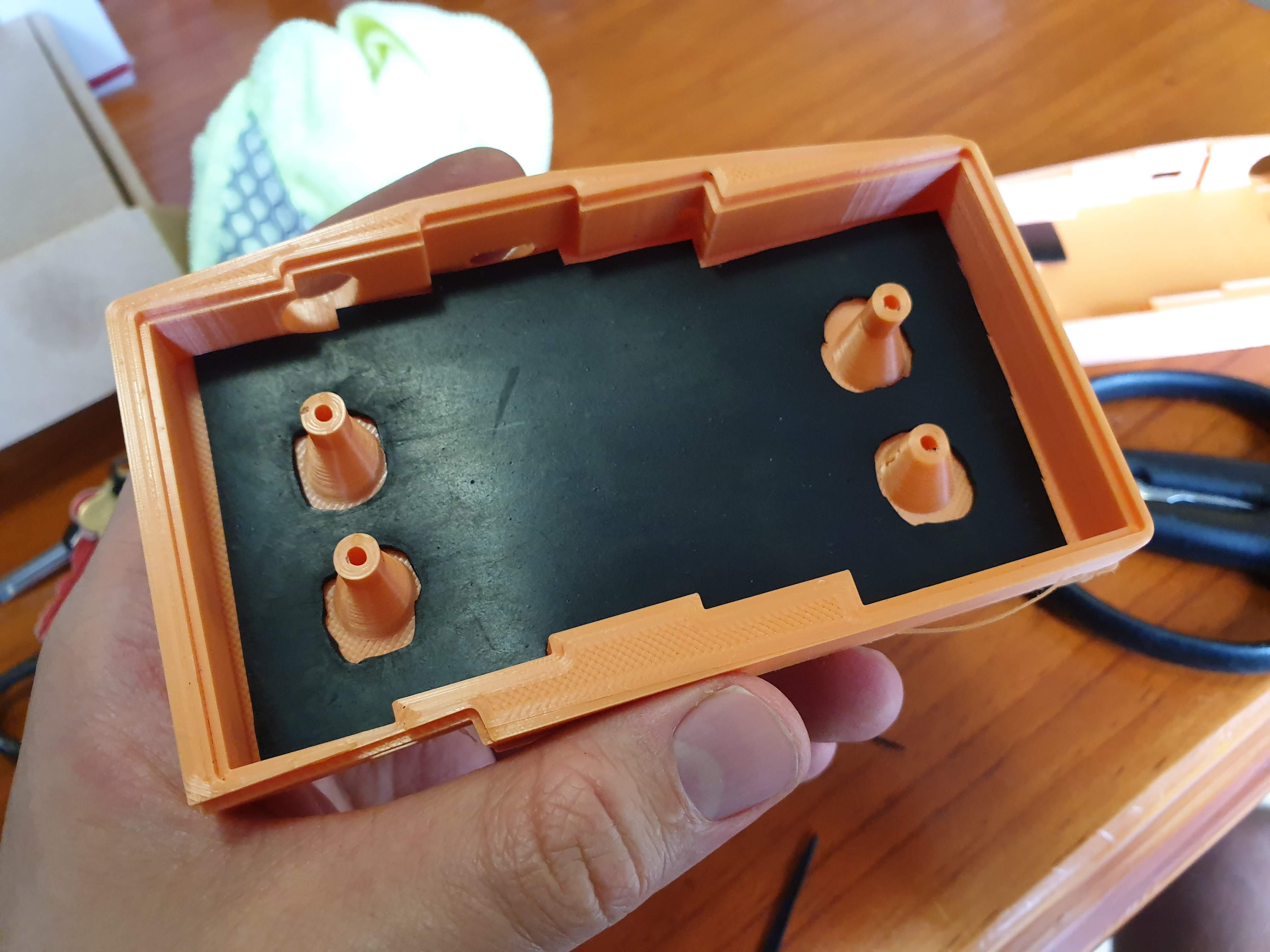
Dampening
I wanted a quieter build than my last, so thought I’d add in a little dampener for good measure. I bought some neoprene and cut it to fit. I never did any testing comparisons, with and without, so I’m not even sure if it made any difference!
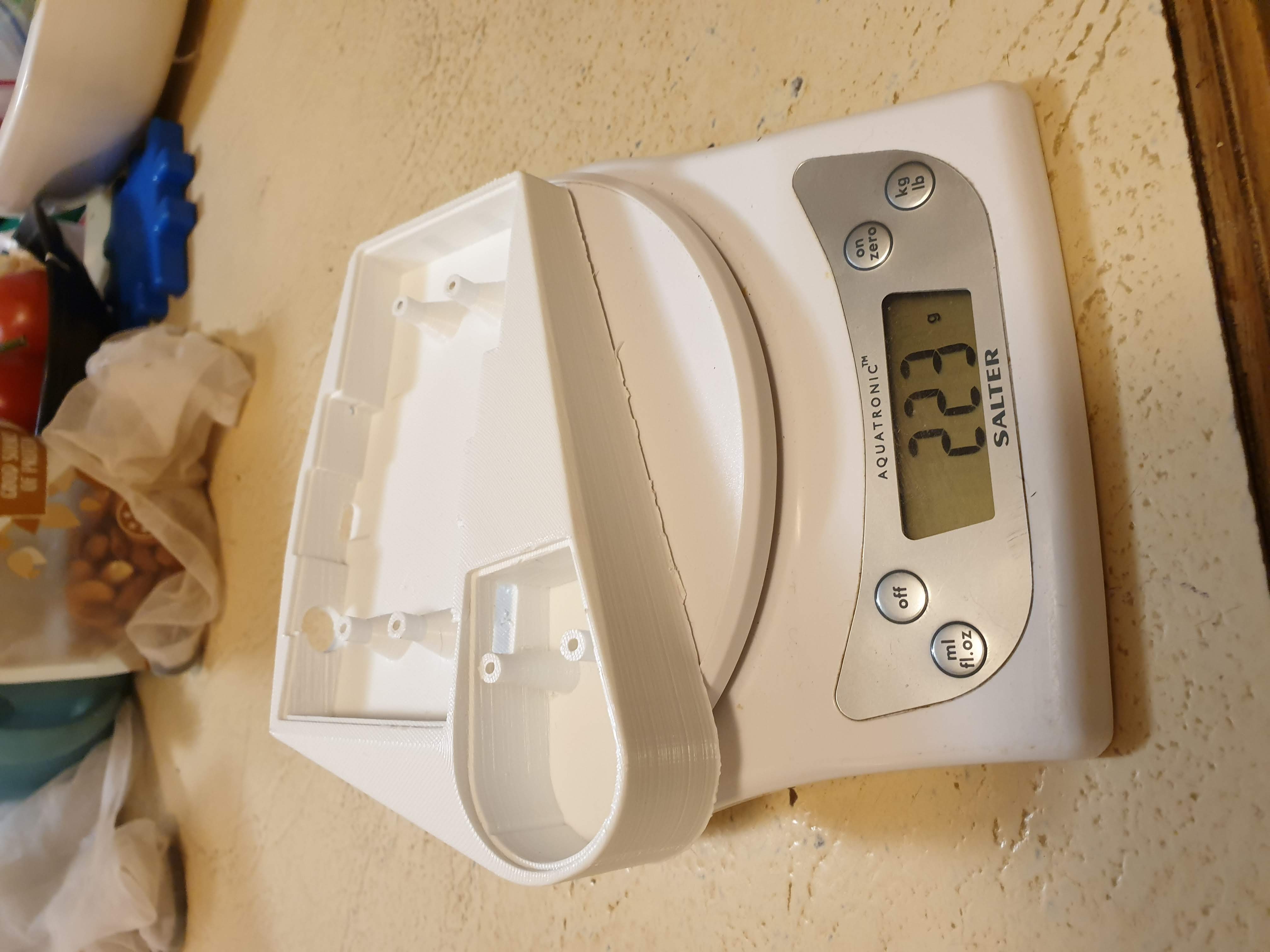
Printing
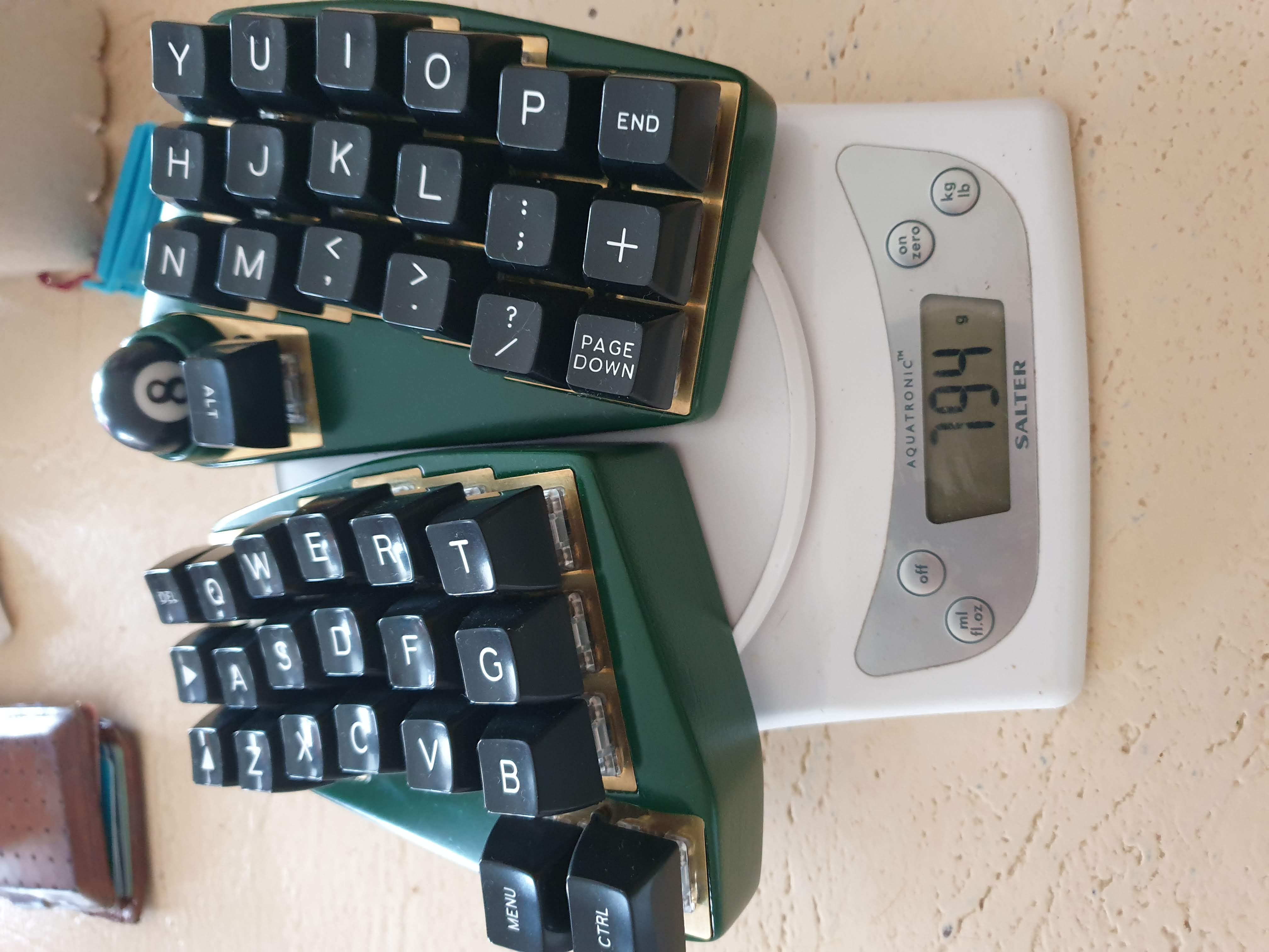
I decided to the 3D print at 100% infill. It wasn’t really required, and was overkill, in terms of stength, but I wanted to give it as much weight possible. The prints alone ended up weighing about 200 grams each. This ended up taking around 50 hours per side!
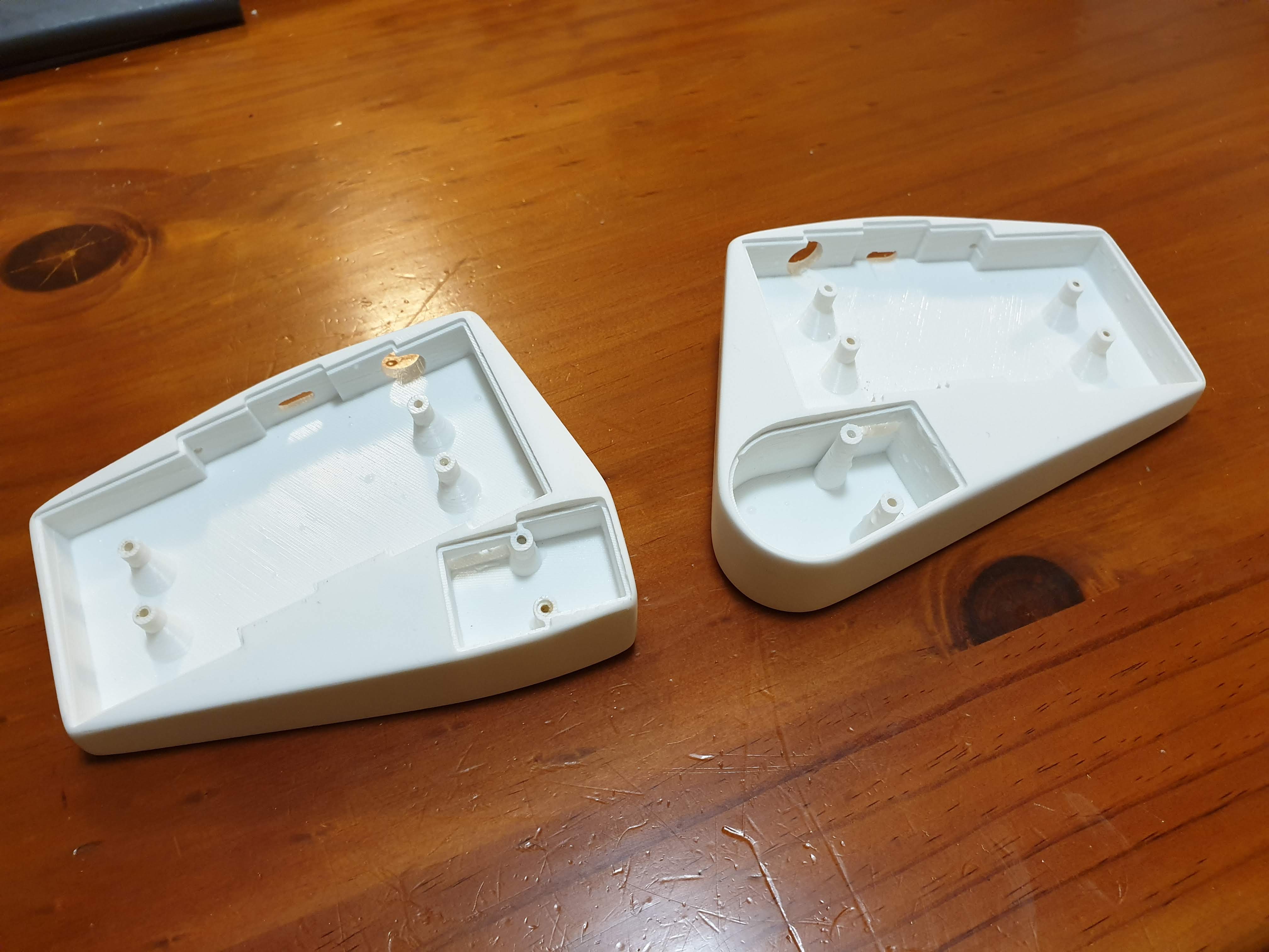
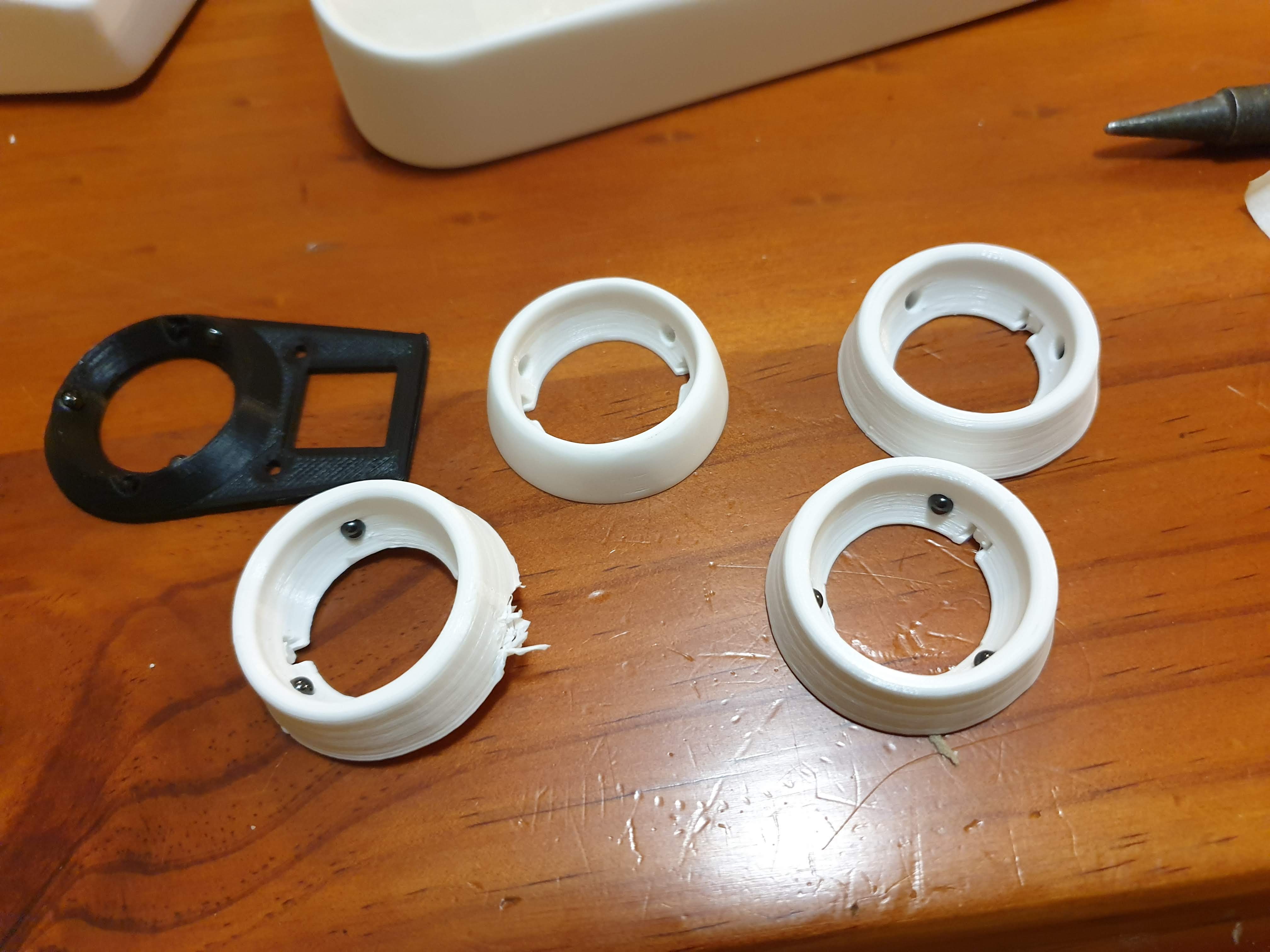
Due to various tolerences, it took a fair few attempts to get the trackball mount ring just the right size for my ceramic bearings to press fit.
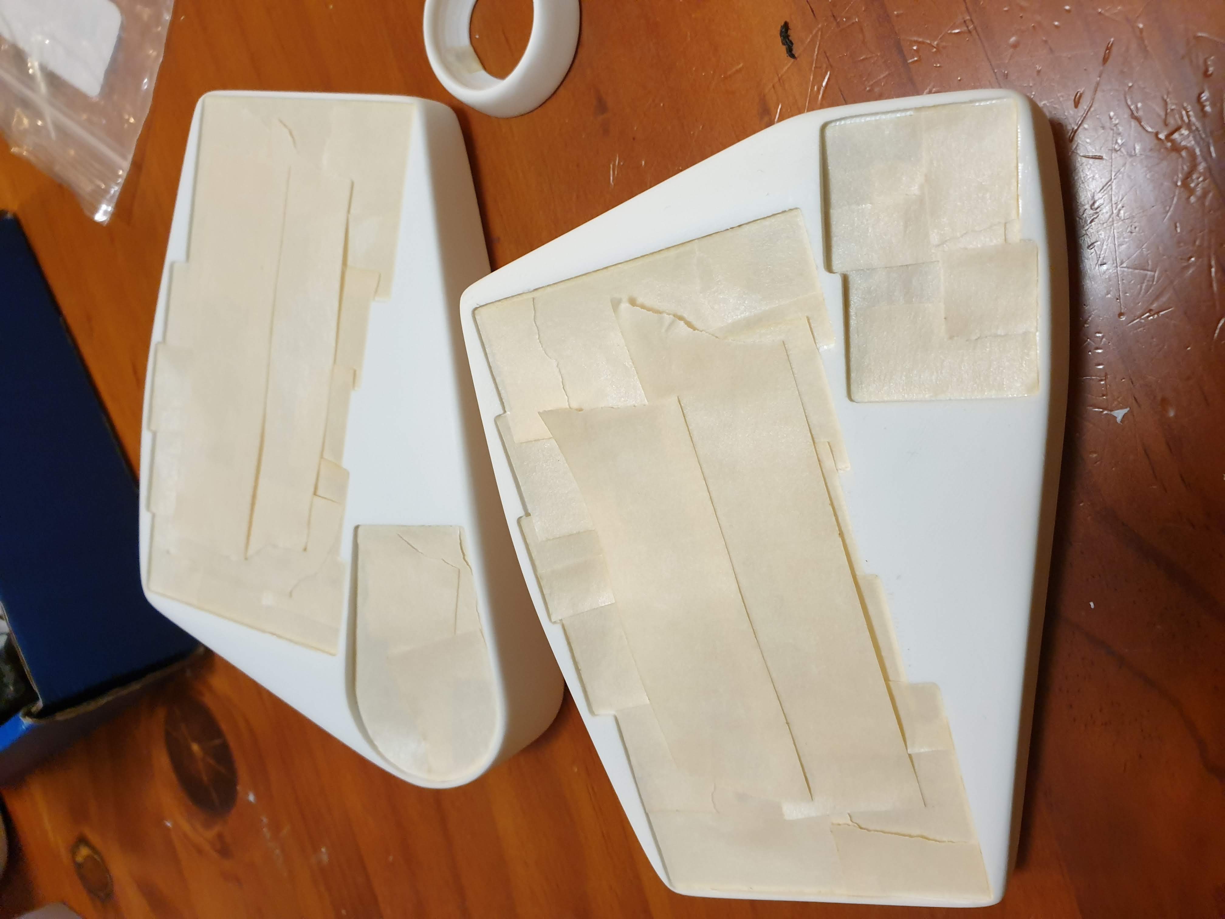
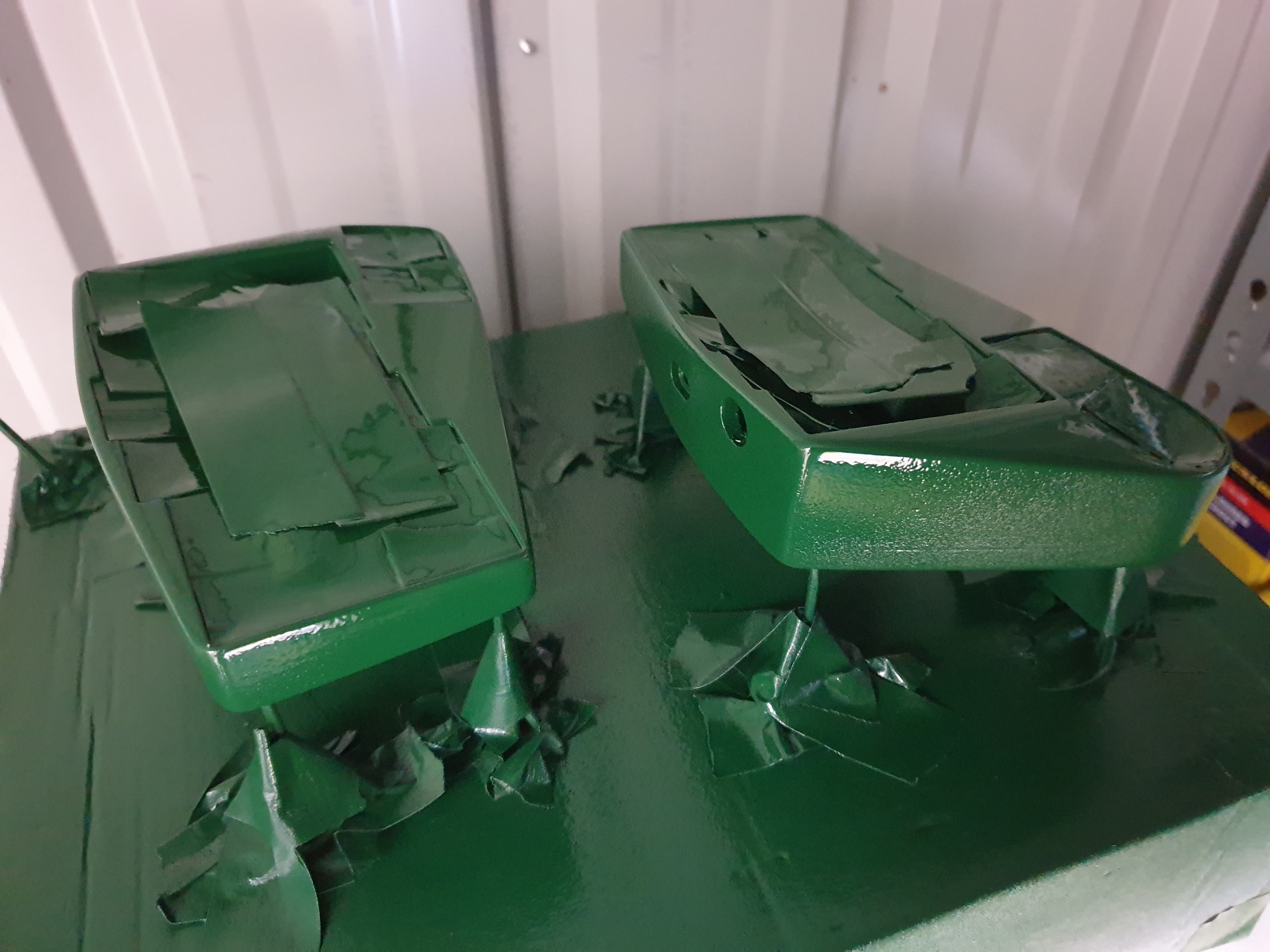
Painting
I did similar to my last build, but skipped the primer. I did two to three coats of “hunter green”, and two coats of clear coat (satin). I used Rust-Oleum; it was only slightly more expensive, but in my previous build I’d found it sprayed better and gave a better colour that some of the cheaper brands I’d tried. I rushed it a little, trying to fit it in with weather and two small chilren’s sleep patterns, so the end result wasn’t quite as neat as my v1 build.
Closing throughts
I’m really happy with how this build turned out. It succeeded with:
- better trackball position
- better sensor
- better sensor mount
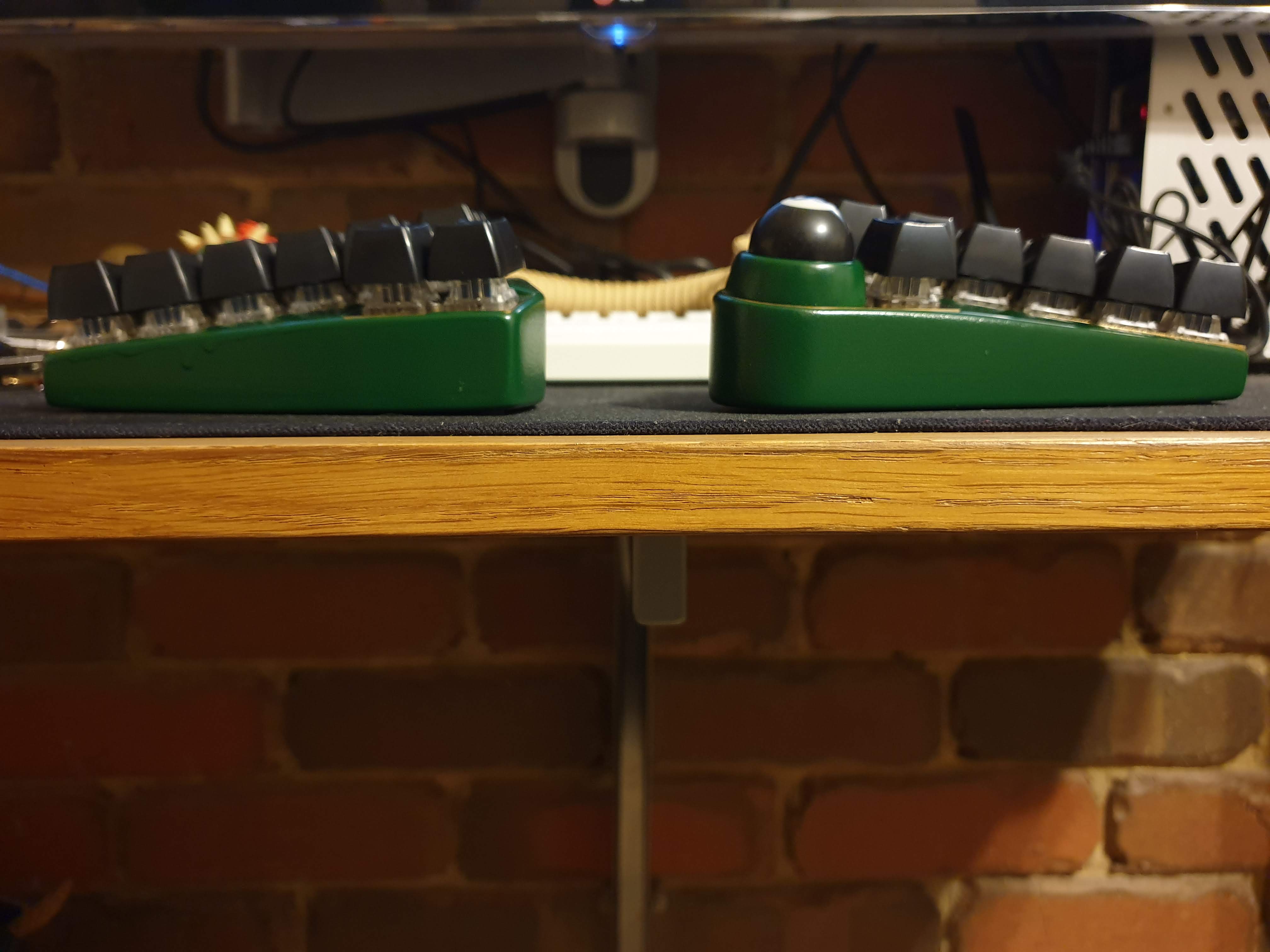
- lower profile case
- better typing angle
- trackball mount more enclosed
- easier to build
- less buggy code
- more maintainable code
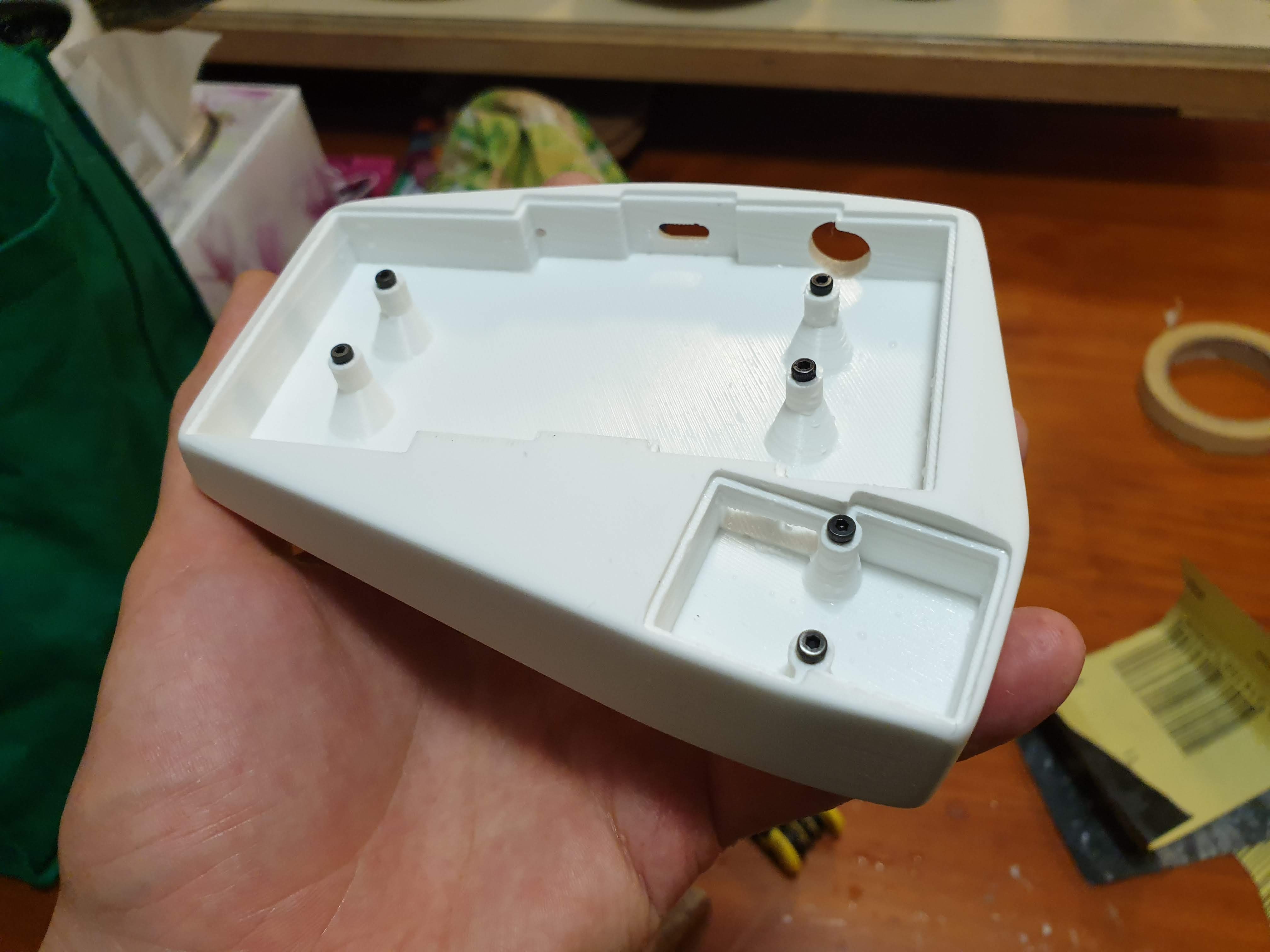
But… there are still a few niggling issues. It is still a pretty hard keyboard to build and assemble. I wish I’d used threaded inserts for the bolts rather than using nuts on the opposing side. I could have taken my time and done a better paint job. I could have merged the hand and thumb PCBs into a single file for cheaper manufacturing.
However, a few people have managed to make their own builds of this design, and with the cleaner code base for others to potentially use or hack away at, I’m happy to leave this project for now. I’ve got a keyboard that really suits my needs and that I love using. I’ll hopefully be able to use it for many years. And if it ever finally breaks down, maybe I’ll finally get around to perfecting it… for the third time.