v2 Build Guide
Bill of materials
| Part | Quantity | Link/Store | Notes |
|---|---|---|---|
| Elite C | 2 | Keebio | This store URL now links to a v4 controller, which requires different case files, and which are not yet tested |
| Mill-Max Low Profile sockets (or equivalent headers) (strip of 12 at 2.54mm) | 4 | SplitKB | |
| ADNS 9800 or PMW 3360 breakout board | 1 | ADNS PMW | |
| TRRS socket PJ-320A | 2 | Amazon | |
| Reset switch | 2 | Sparkfun | |
| Through-hole diode | 39 | Amazon | |
| Through-hole 4.7k resistor | 2 | Amazon | |
| Hand plate | 2 | GitHub | Recommend 1.5mm thick when manufacturing |
| Left thumb plate | 1 | GitHub | |
| Right thumb plate | 1 | GitHub | |
| Hand PCB v2.1 | 2 | GitHub | |
| Thumb PCB v2.1 | 2 | GitHub | |
| Male-to-male TRRS cable | 1 | ||
| USB Type-C cable | 1 | To connect keyboard to host (e.g. PC); you probably want USB-A on the other end | |
| Left case | 1 | GitHub | If using an Elite C v4, you can try using these untested case files, as the USB cutouts will be slightly different |
| Right case | 1 | GitHub | If using an Elite C v4, you can try using these untested case files, as the USB cutouts will be slightly different |
| Bearing mount | 1 | GitHub | |
| ADNS or PMW cover | 1 | ADNS PMW | |
| Right-angled pin headers (strip of 4 at 2.54mm) | 4 (x4) | SparkFun | Will need stacked pin headers if using the ADNS9800 |
| 4 pin jumper wire ~10cm | 4 | Amazon | Only needs the pin sockets at one end, but if two-ended (female-to-female), can just chop one end off |
| 18mm M2 bolts | 12 | ||
| 22mm M2 bolts | 2 | ||
| M2 nuts | 14 | ||
| Balls to support trackball, 3.175mm diameter | 3 | Amazon | |
| 0.98” / 25mm diameter trackball | 1 | Mini pool balls | Any hard, low friction 0.98” / 25mm diameter ball will suffice |
| MX style switch | 39 |
Steps
Each half of the keyboard has L and R annotated for each component, corresponding to the left and right sides respectively. When soldering components, insert them from the side that matches their letter.
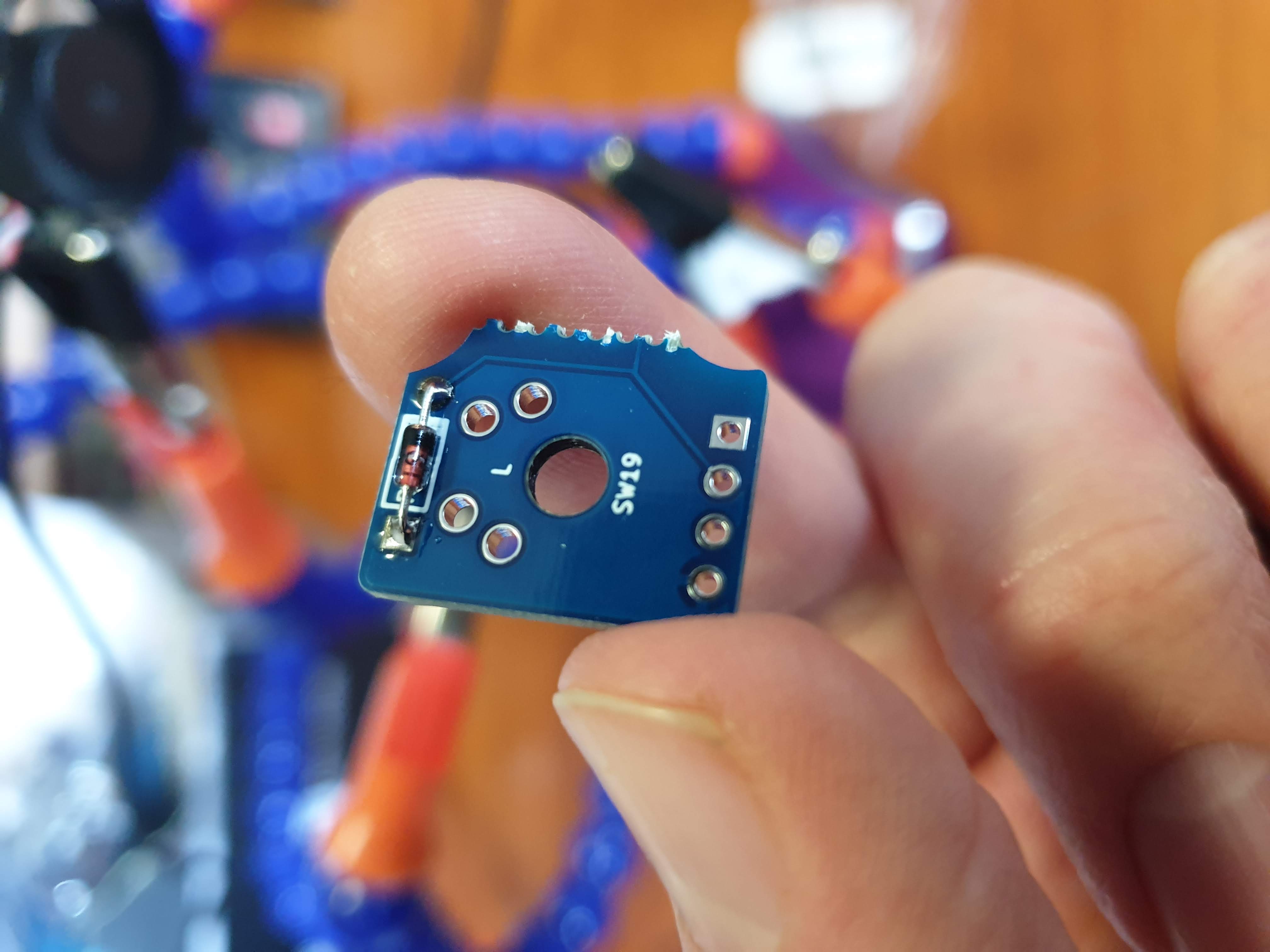
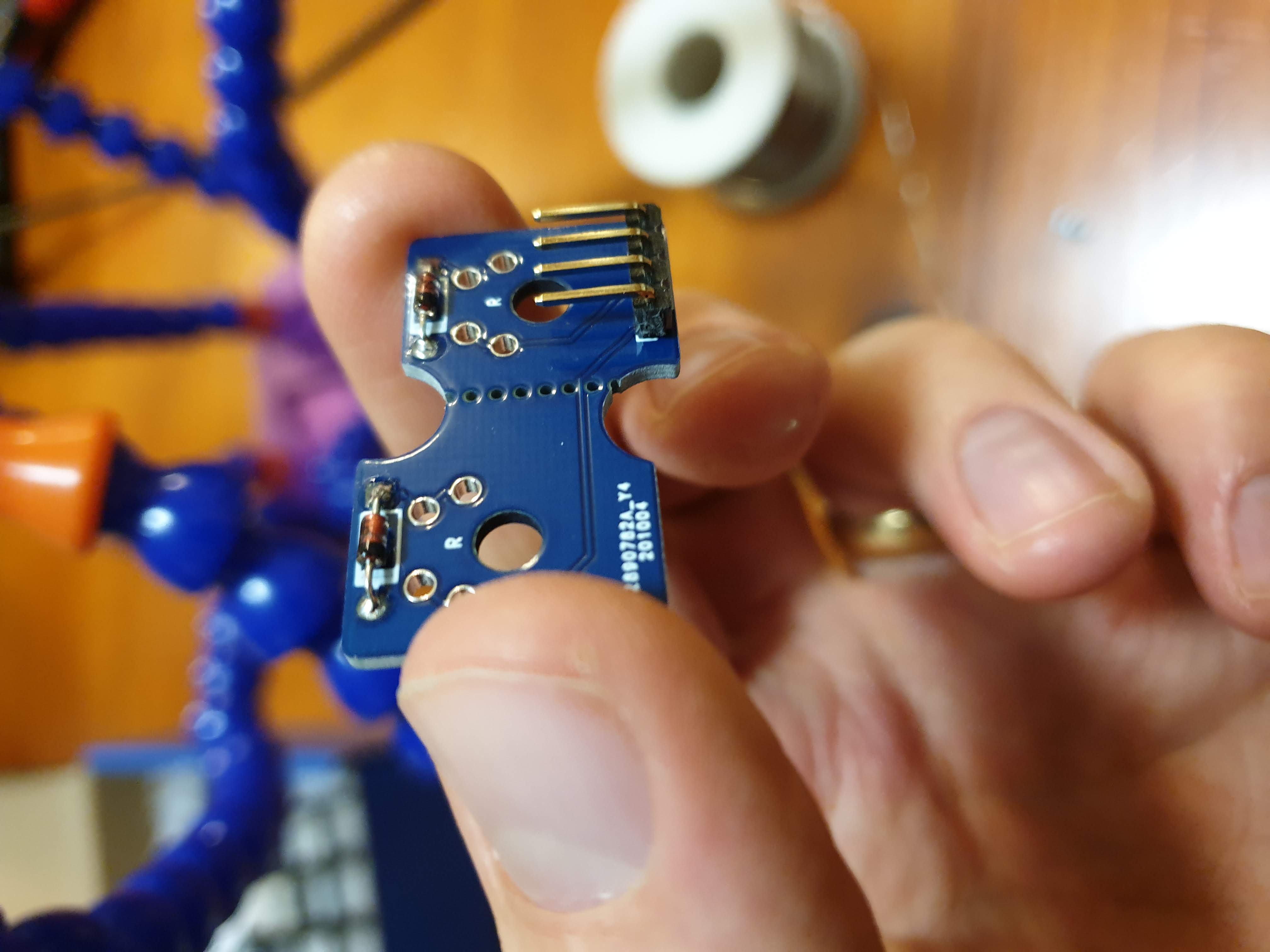
1. Snap
Grab some pliers, or two pairs, and break one of the thumb PCBs in half.
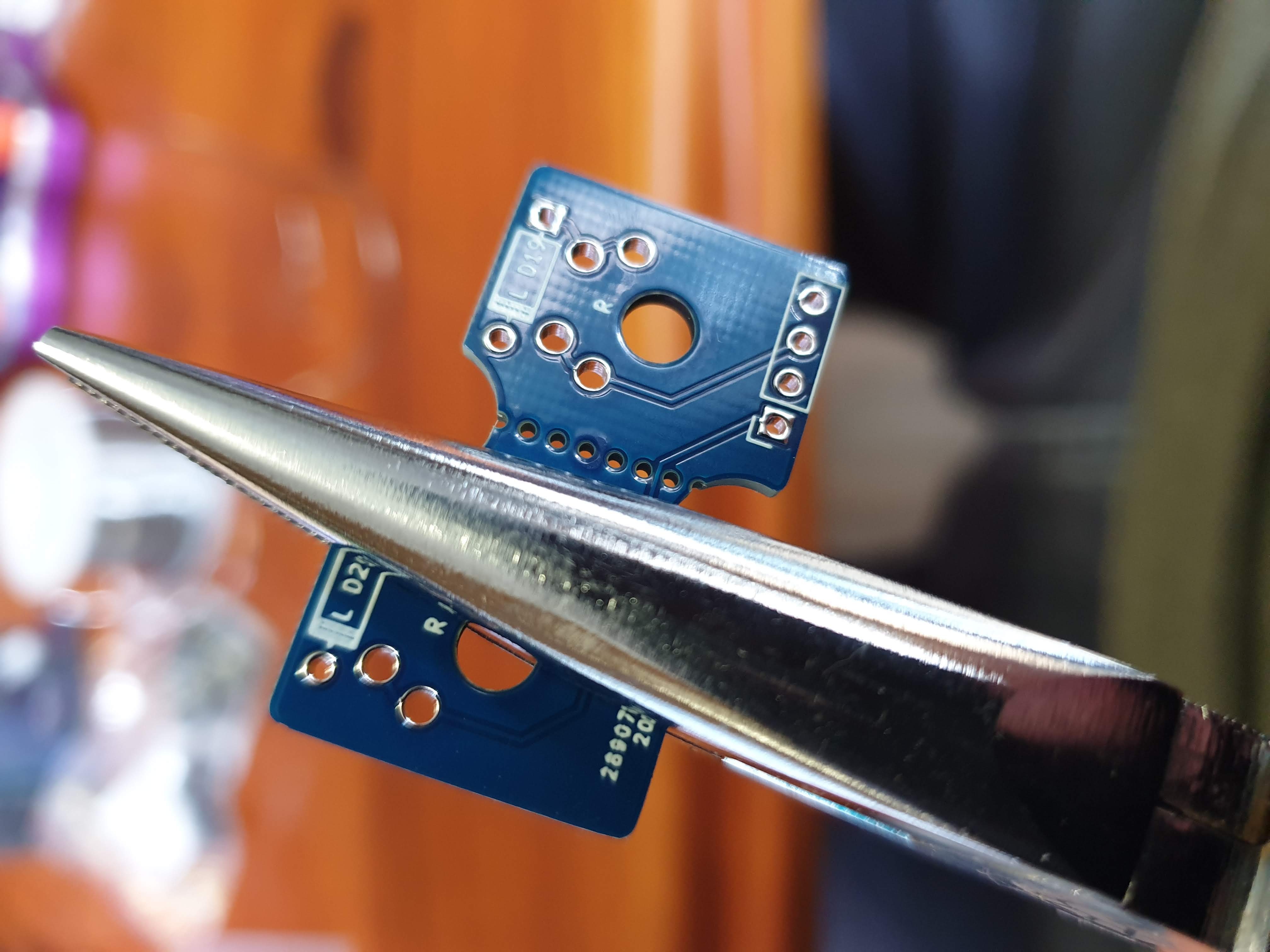
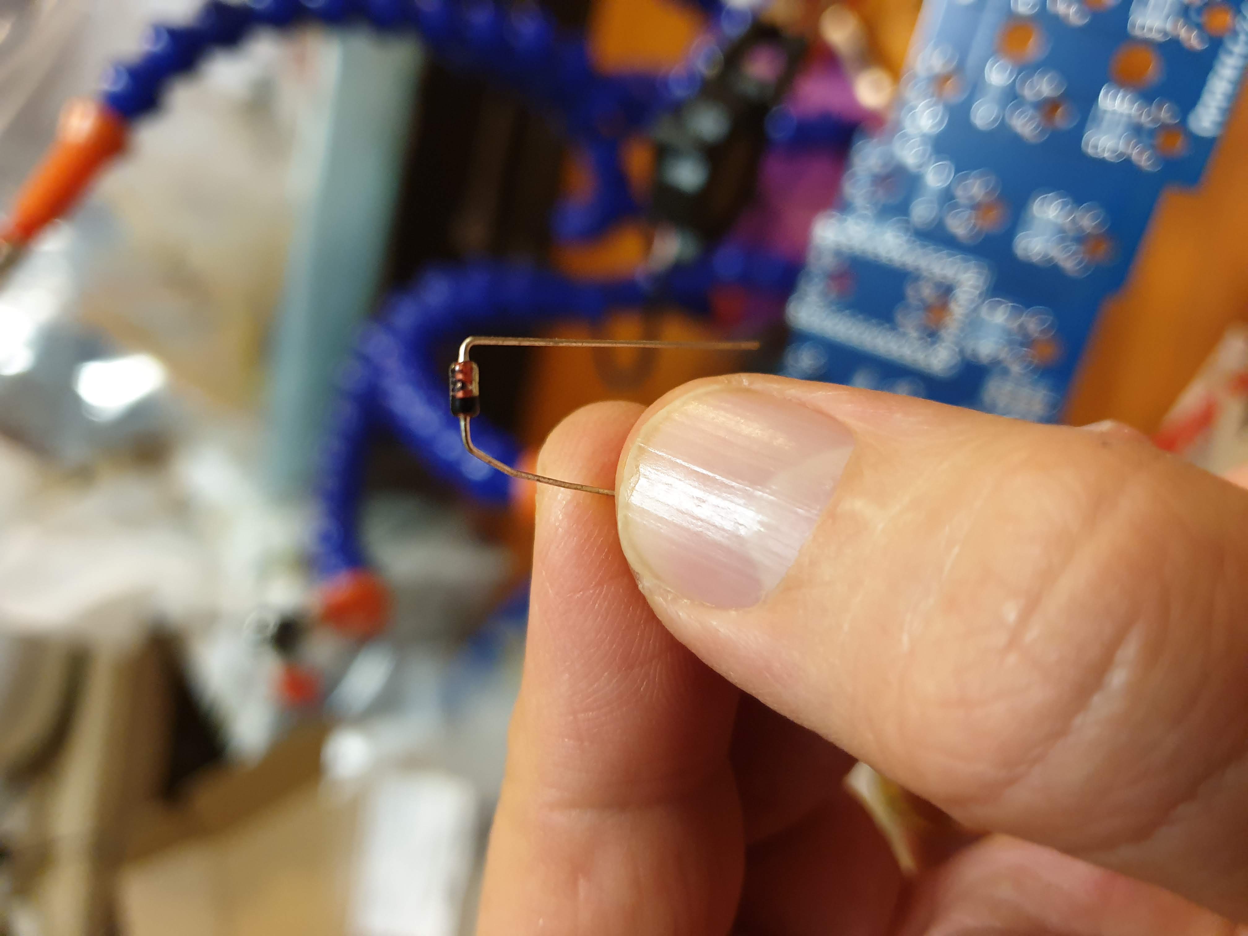
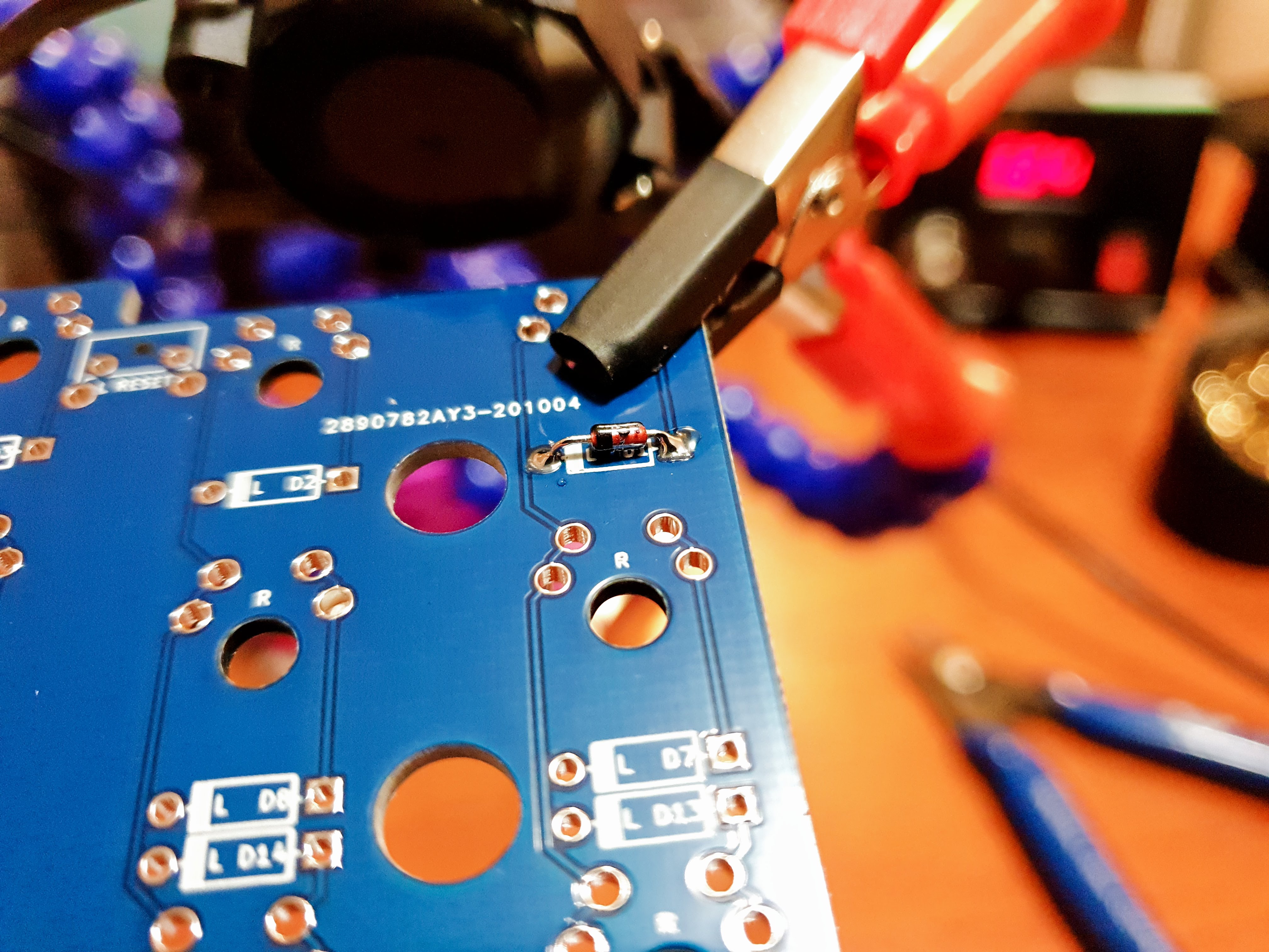
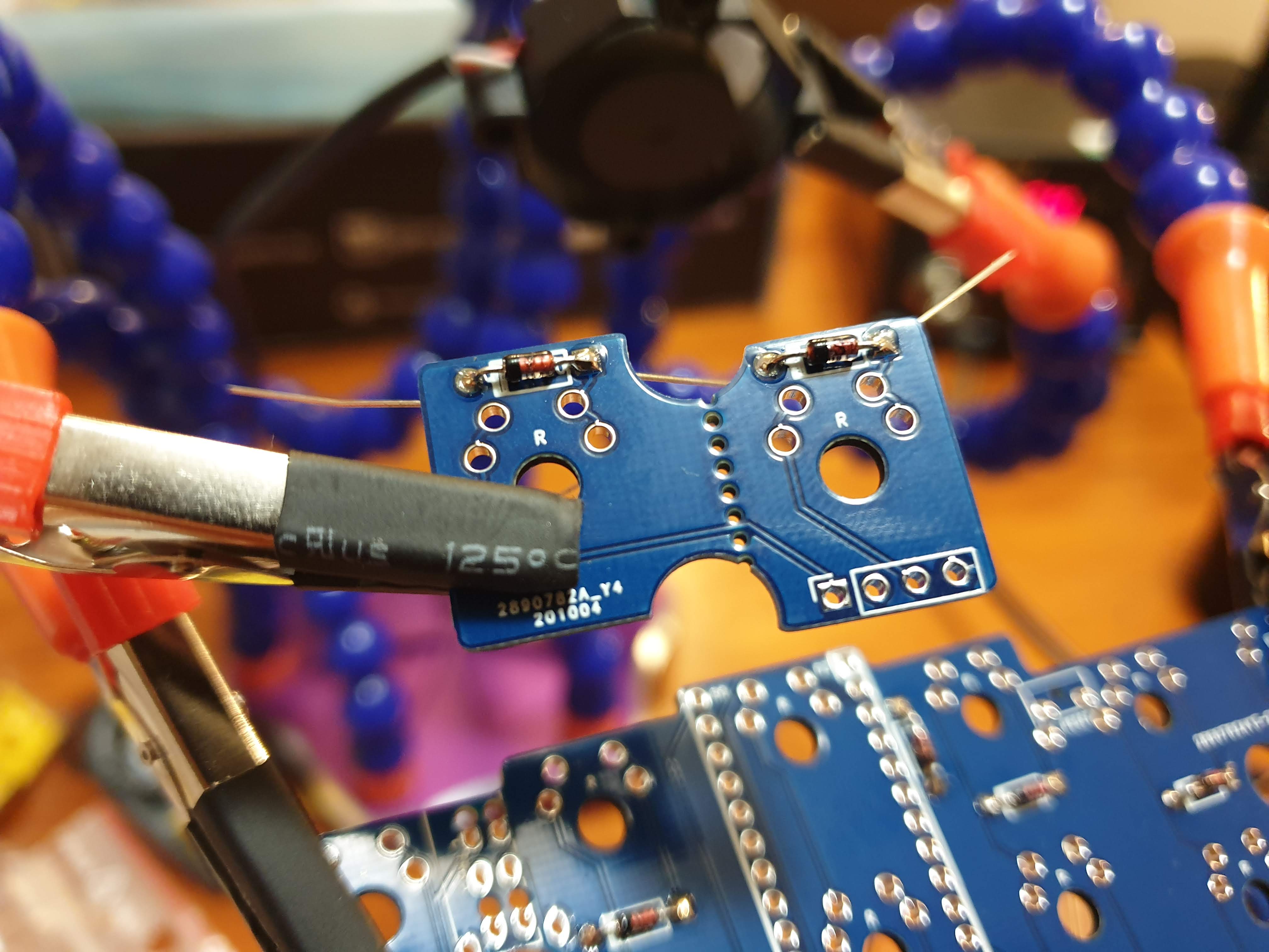
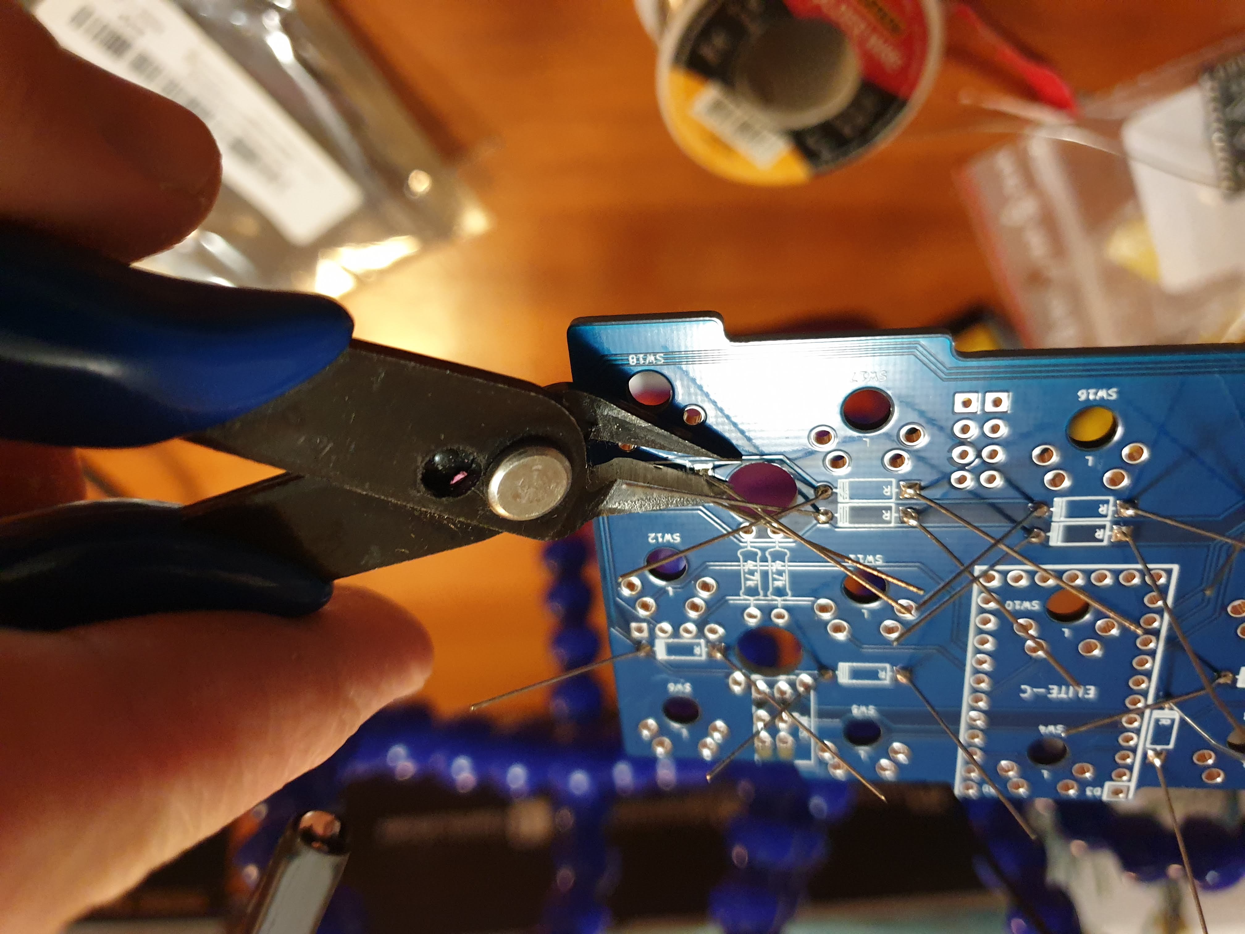
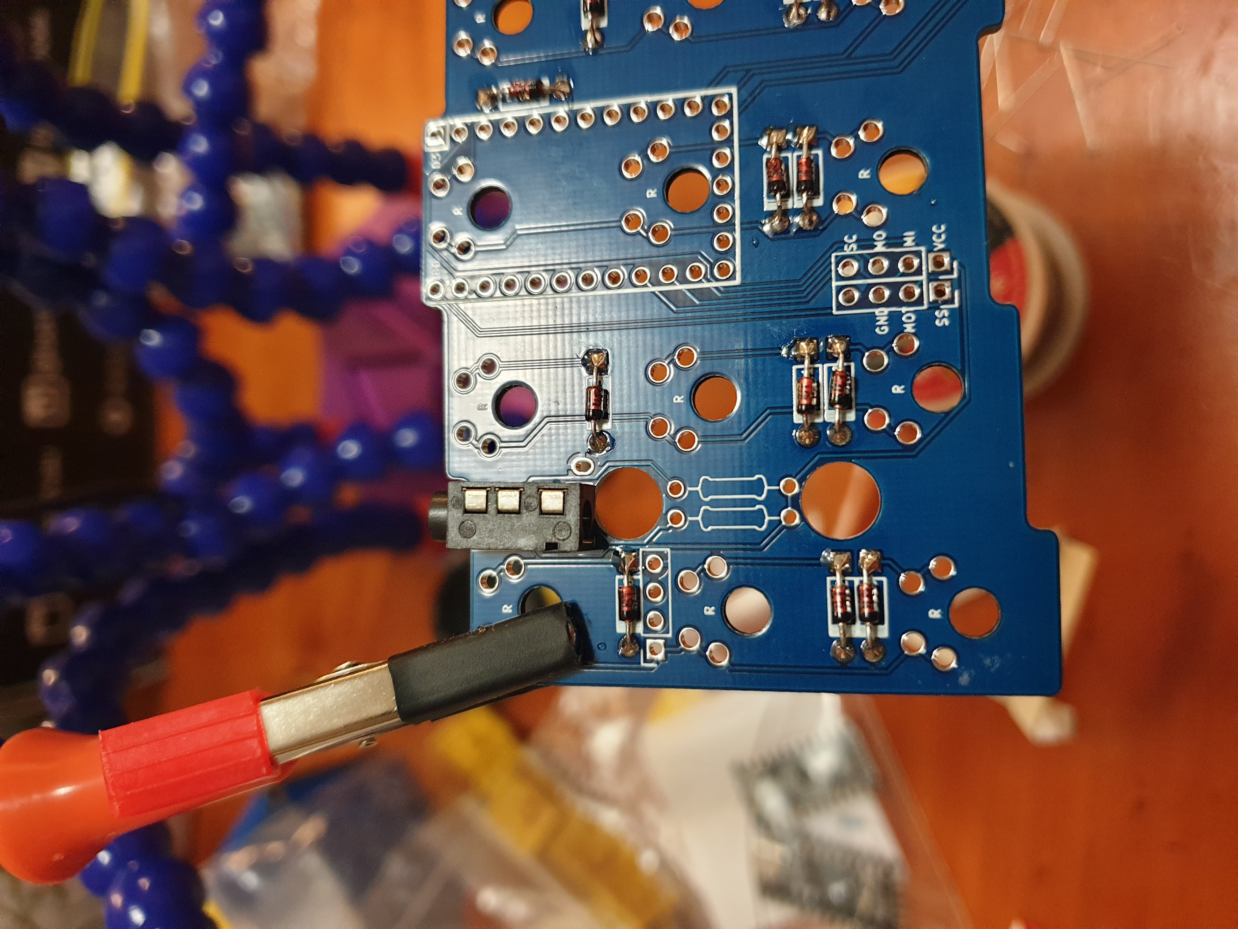
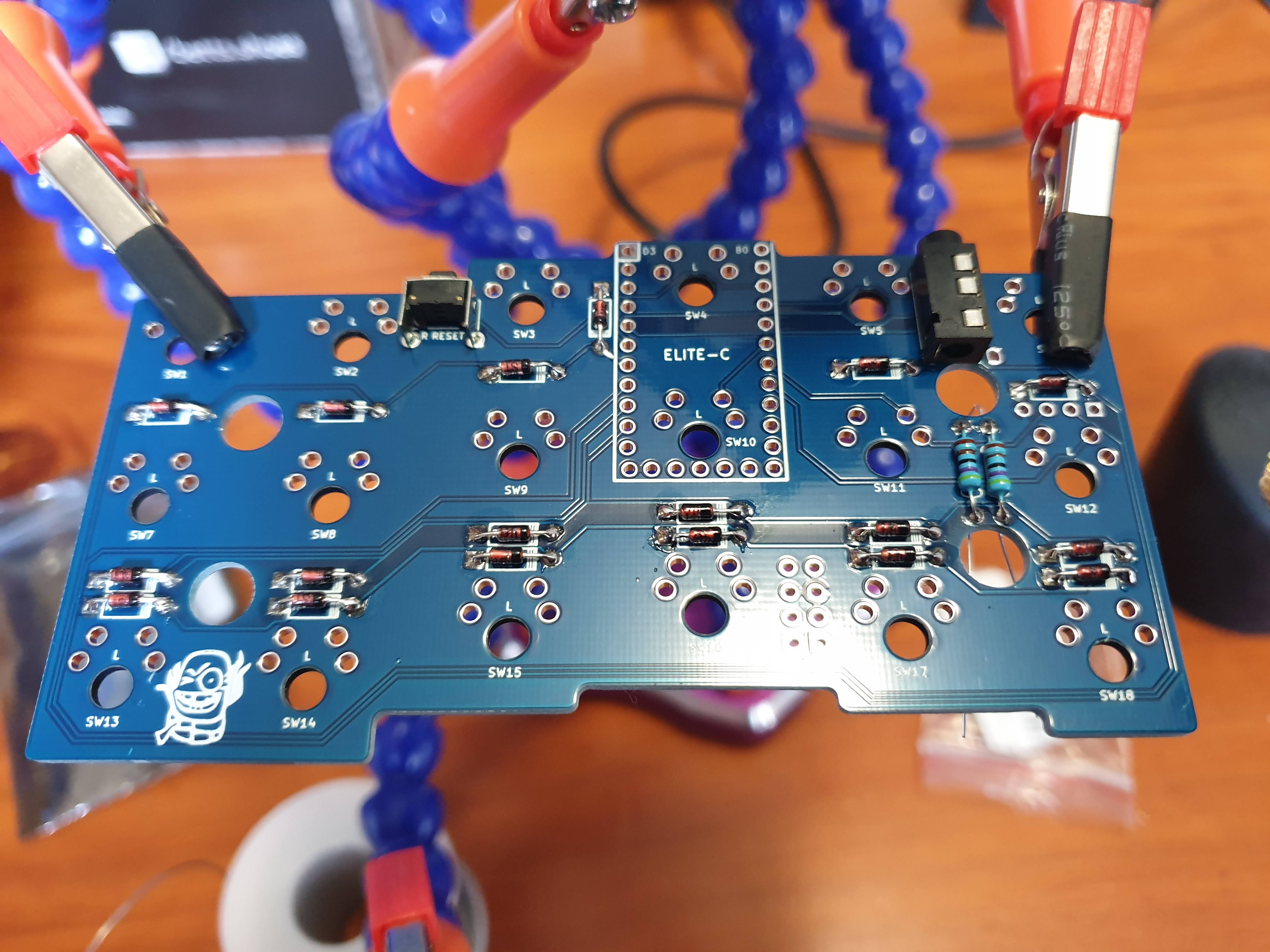
2. Diodes
On the bottom of the PCBs, solder on diodes, marked on the silk screen square rectangles with a black line on one end. The black lines on the diodes (cathodes) should align with the black lines on the silkscreen. On the right thumb PCB, you only need to do the diode above the 4 breakout pin holes. Use flush cutters to snip off the diode legs after soldering.
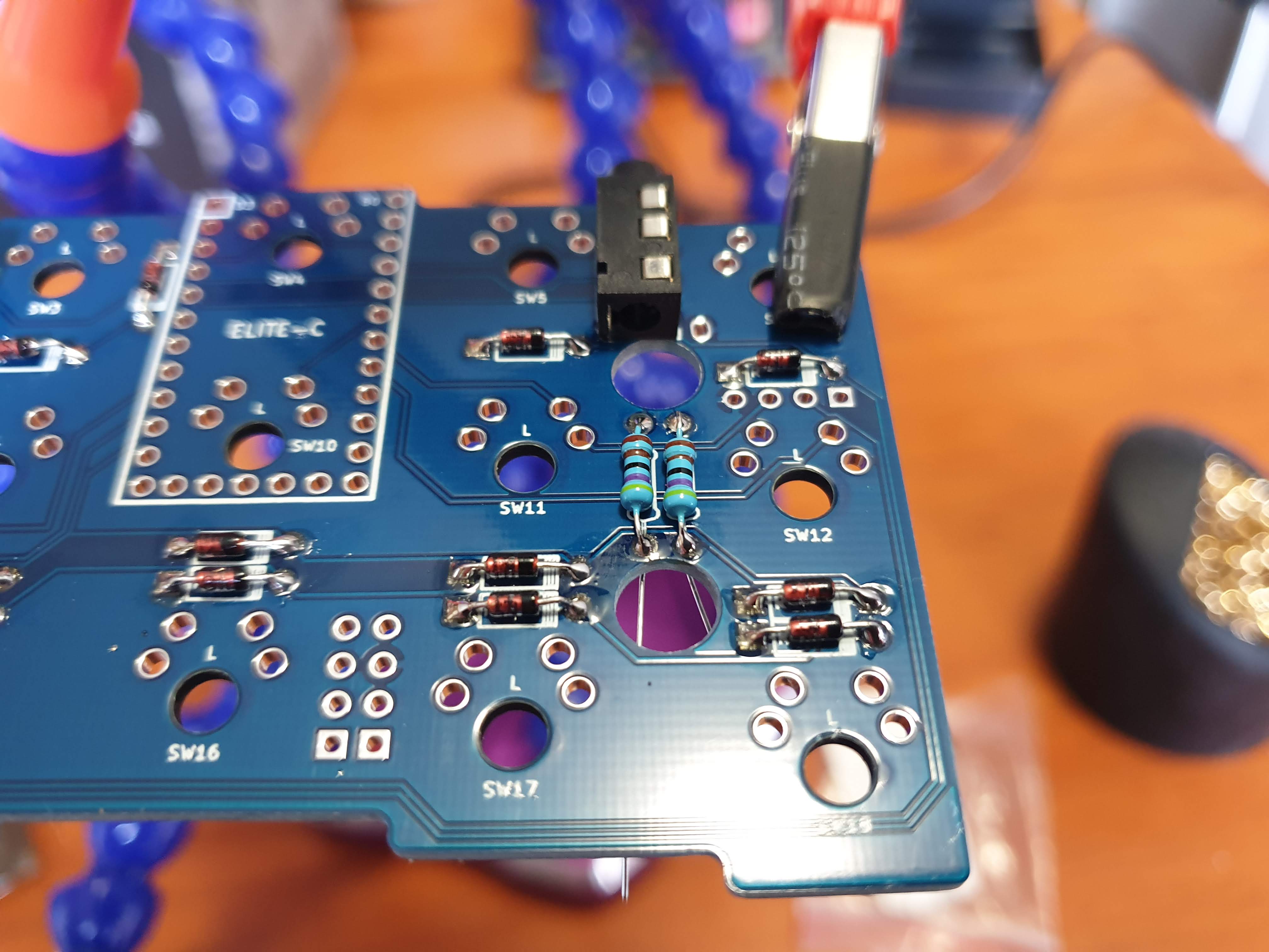
3. Resistors
Resistors only needed to be added to the bottom of the right side of the keyboard; the orientation doesn’t matter.
4. TRRS jacks
A TRRS jack needs to be added to each side of the keyboard.
5. Reset switches
A reset switch needs to be added to each side of the keyboard.
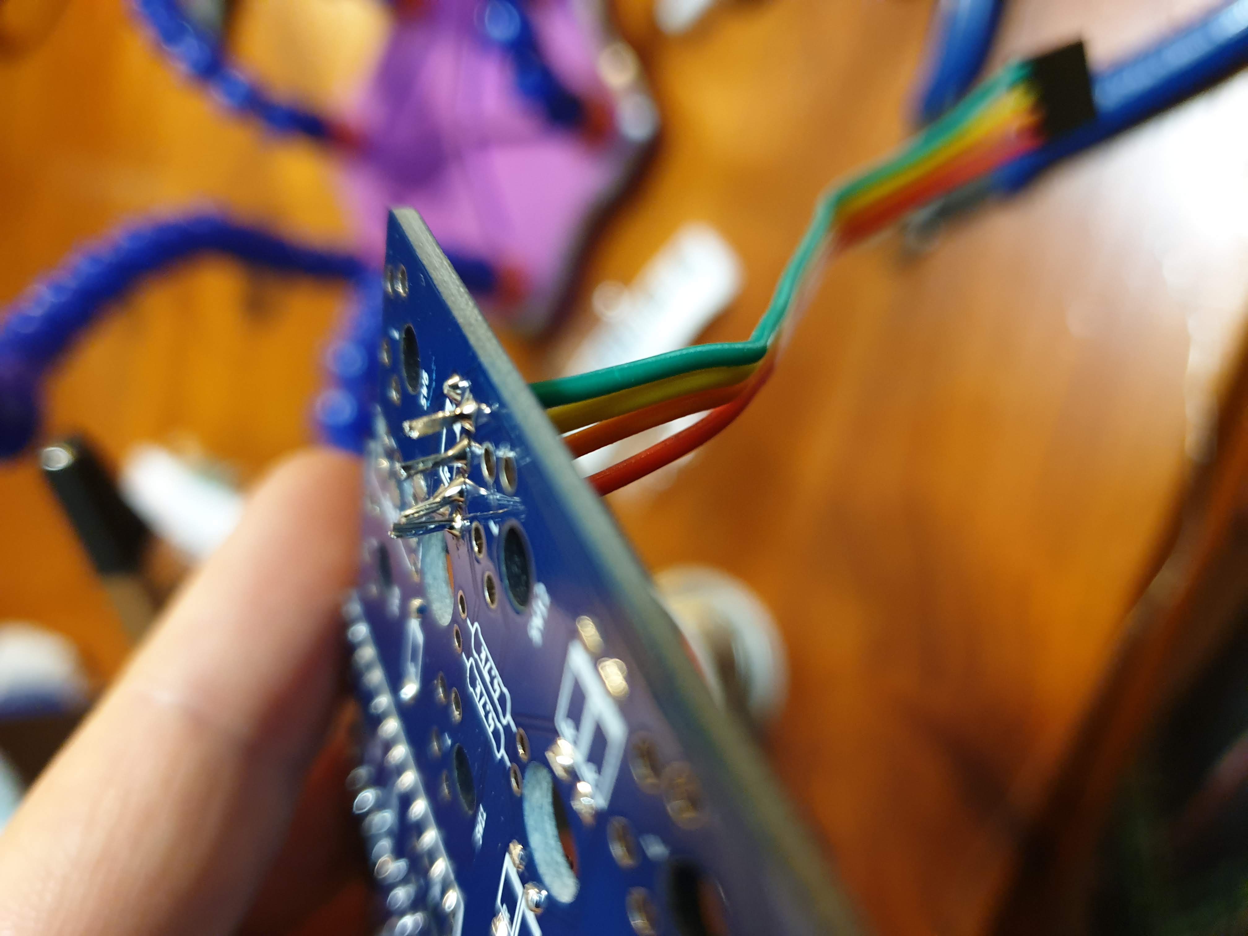
6. Pin headers
While the wires could just be soldered directly, it is a lot easier to assemble or disassemble the keyboard with pluggable sockets and headers. If you have a female-to-female jumper wire, snip of the socket at one end.
One the left side, solder the four ends of one jumper cable into the 4 breakout holes next to the resistors.
One the right side, do as above. Also, solder two jumper cables into the 8 breakout holes near the bottom edge of the board.
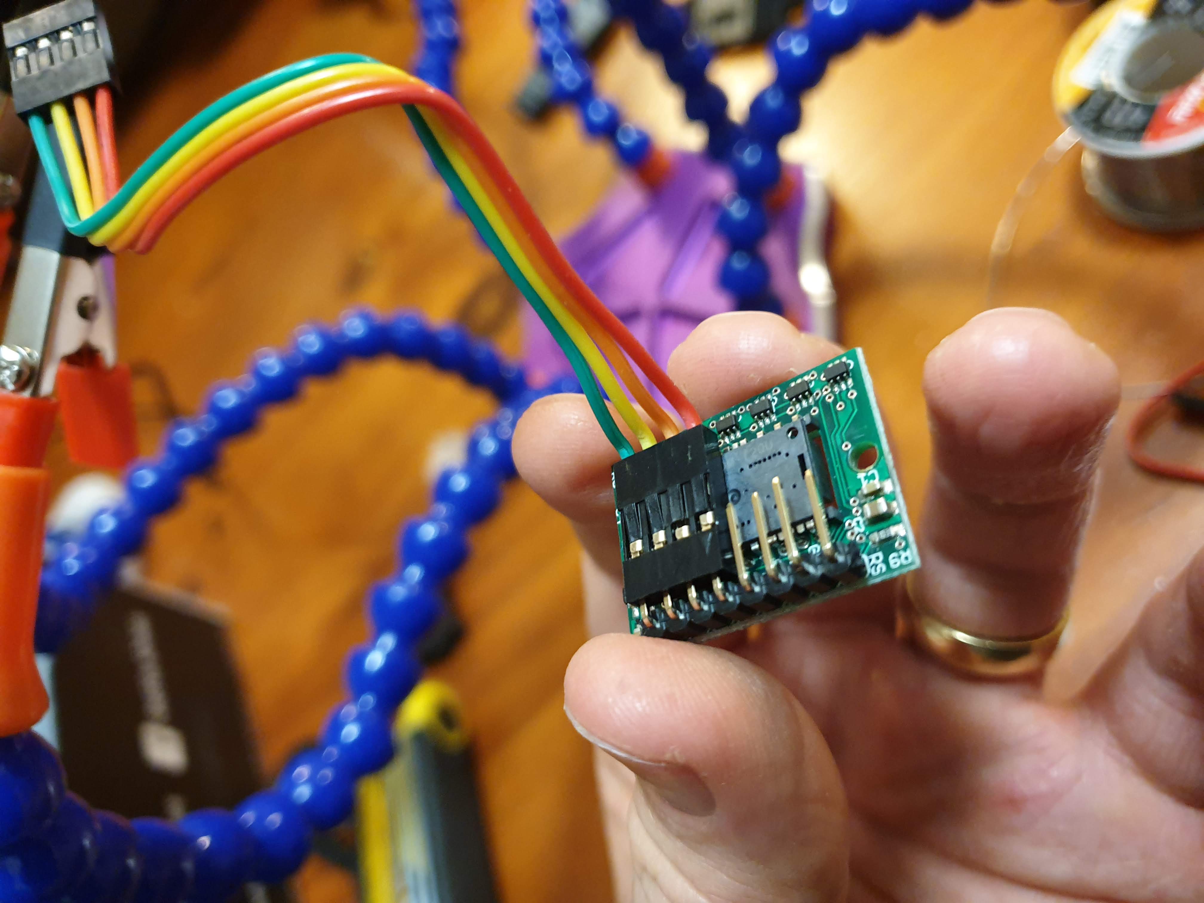
Headers are needed on the thumb PCBs for the wires to attach to. On both thumb PCBs, solder on a set of right-angled headers.
Headers are also needed on the respective sensor breakout board. For the ADNS, use 2x4, stacked, right-angled headers. For the PMW, use a strip of 8 headers.
7. Flashing Elite Cs
Checkout my QMK fork from GitHub. See the QMK docs on how to set up your build envioronment.
Following are the default build comands for various configurations:
| Sensor | PCB version | Command |
|---|---|---|
| ADNS | 2.0 | make oddball/v2:default |
| PMW | 2.0 | make oddball/v2:pmw3360 |
| ADNS | 2.1 | make oddball/v2_1:default |
| PMW | 2.1 | make oddball/v2_1:pmw3360 |
To customise functionality, make a new keymap.
Special keycodes added for the Oddball keyboard are:
| Keycode | Function |
|---|---|
KC_SCROLL | When held, the trackball becomes a scroll wheel |
KC_CPI_1 | CPI option 1 |
KC_CPI_2 | CPI option 2 |
KC_CPI_3 | CPI option 3 |
In your keymaps config.h, you can modify the following:
CPI
// to override a CPI option, where symbol is either CPI_1, CPI_2 or CPI_3, and value is from 1 to 12000
#undef CPI_1
#def CPI_1 9000
SCROLL_DIVIDER
// to override the scroll speed, change SCROLL_DIVIDER, should be a positive number, where larger numbers equals slower scroll
#undef SCROLL_DIVIDER
#def SCROLL_DIVIDER 20
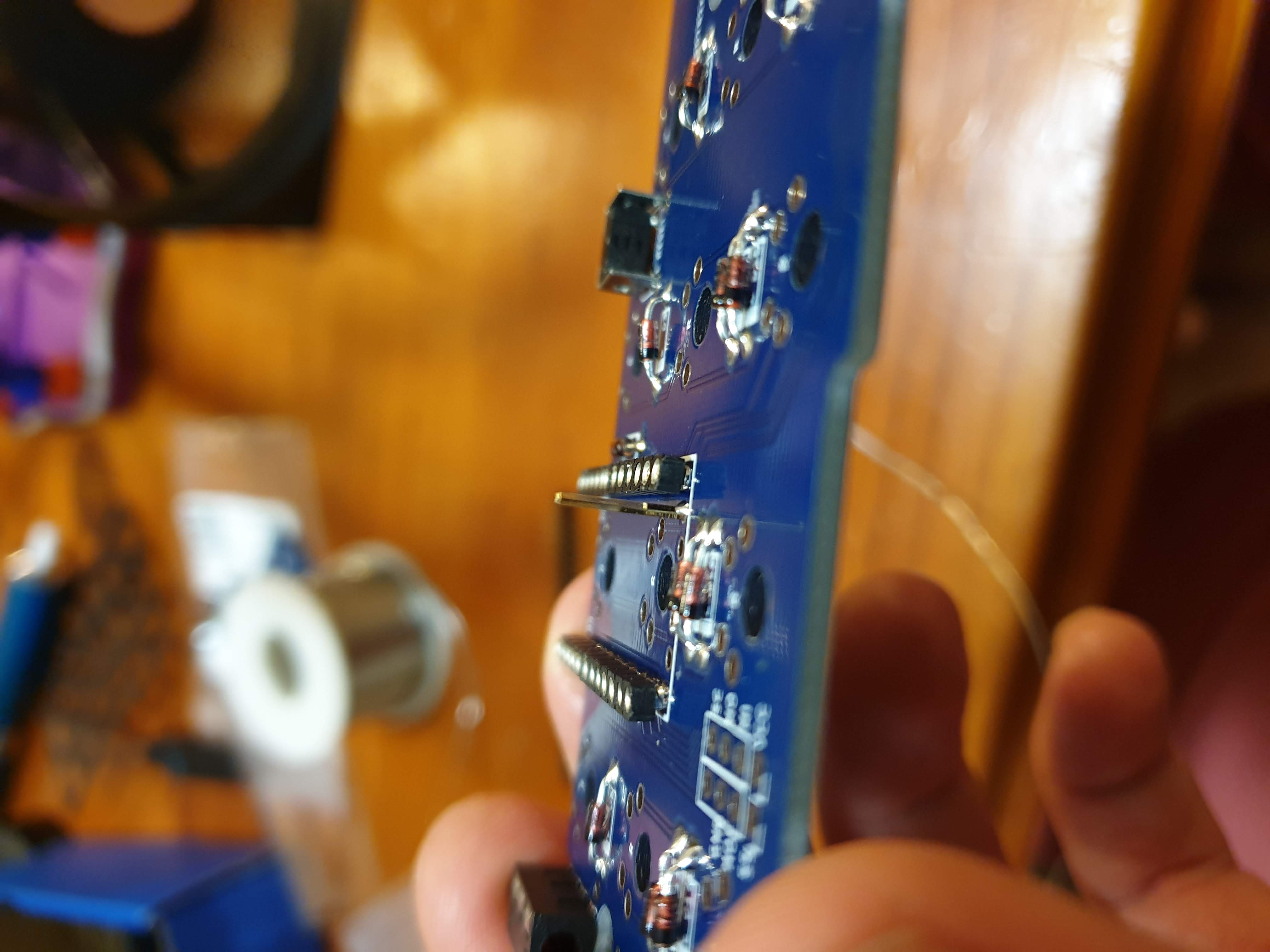
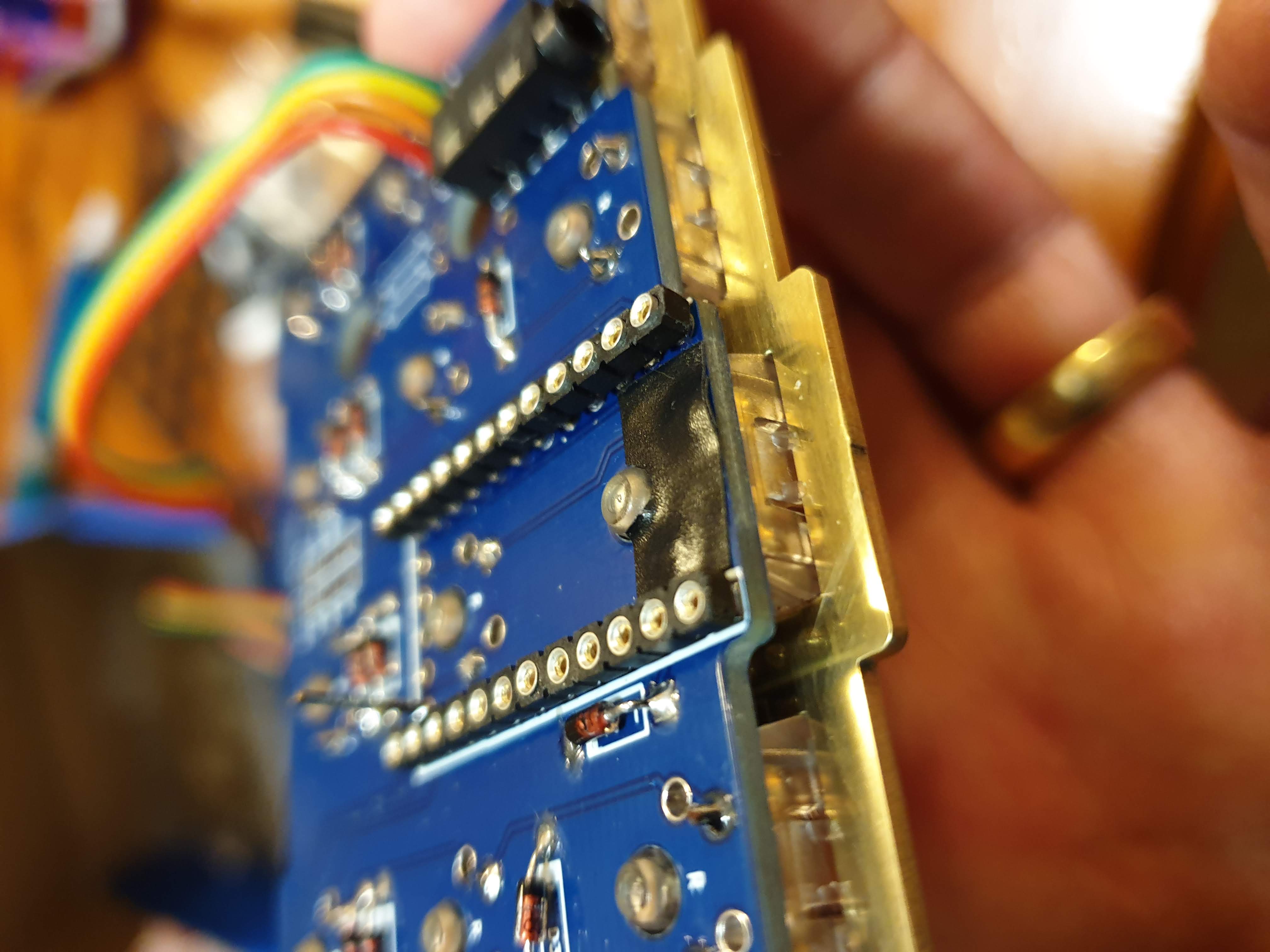
8. Soldering Elite Cs
At this stage you’ll want to solder in the Elite C pin sockets.
None of the v2.X PCBs require the bottom strip of pins to be connected, although the v2.0 PCB requires the right pin as in the following image. This can be done with a single pin header. This in not required for PCBs >= v2.1.
Now the Elite-Cs can be socketed; here is a good guide thanks to 40% Keyboards.
If you want to skip socketing, go ahead. Keep in mind, the case is designed with Mill-Max Low Profile sockets in mind, so you’ll need equivalent headers or spacing to algin the USB-C ports with the case.
9. Testing
To check things are working:
- flash both sides separately over USB
- unplug USB
- link halves with TRRS cable
- plug in thumb modules with jumper cables
- plug in sensor module with jumper cables
- plug in USB to right half
- check keys of both sides are working
- check mouse sensor is working; hovering a finger over the sensor should move the mouse cursor
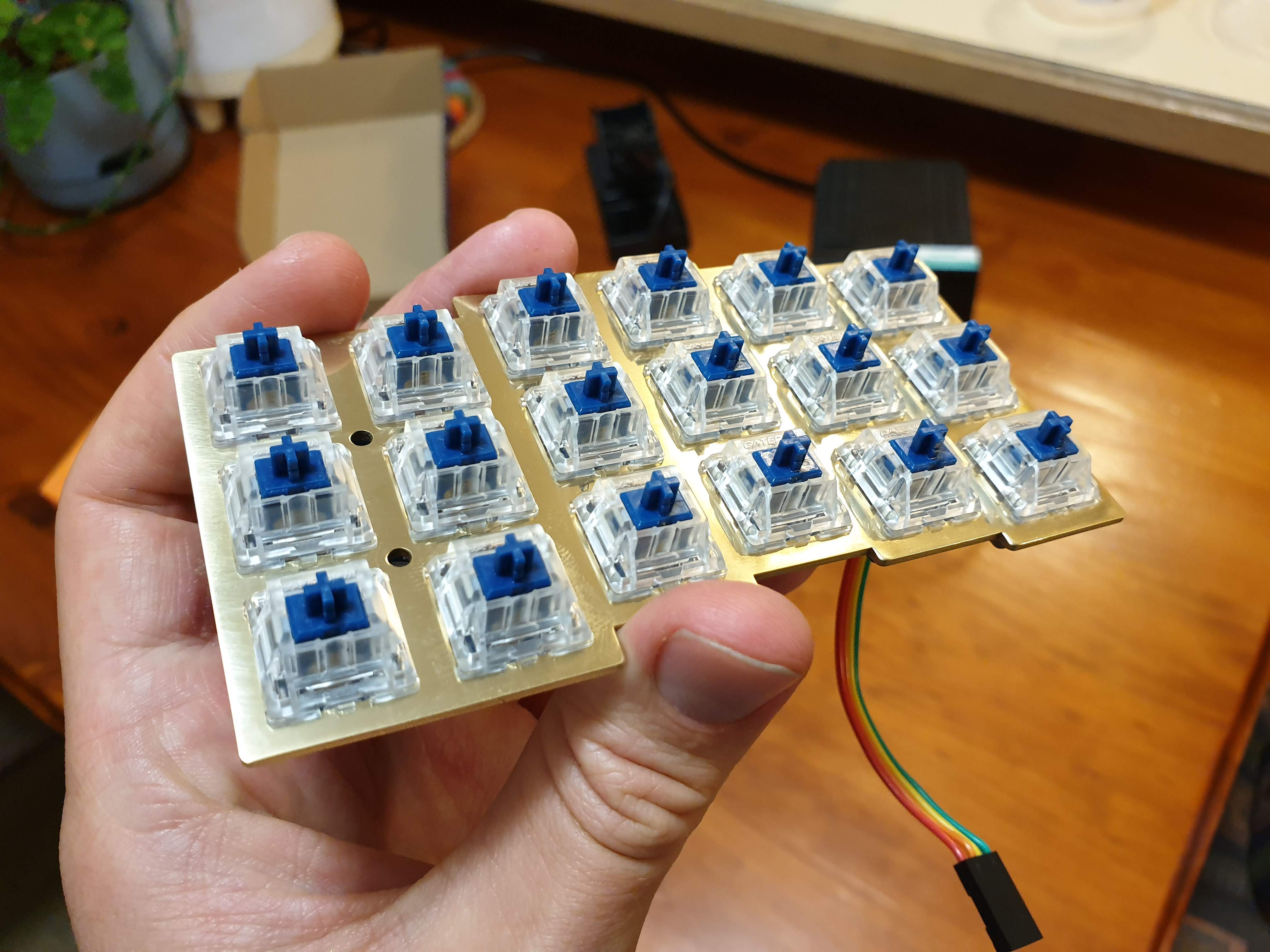
10. Switches
Before soldering the switches in, cut component legs on the top of the PCB as flush as possible. This will give the switches room to sit flush on the PCB. Then solder your switches in; I often start with the corners, then fill in the rest.
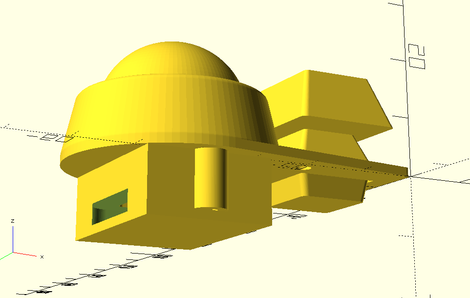
11. Mouse thumb module
Insert the bearings into the trackball ring; it’s a tight squeese, so you may need to use something hard/metal to push them in. Then bolt the ring, plate, sensor cover, and sensor, together with the 18mm M2 bolts and nuts.
12. Assemble plates and modules
- test you can get all the nuts into the underside of the case; it’s a tight fit, and you may need to scratch or dremel our some material to make room
- using some sort of marker or tool, make a note on each jumper set of what the wires/pins are (this will help you know what things are when the plate is inserted an PCB is hidden)
- put in the main hand plates
- check USB and TRRS ports line up with case cutouts; if not, use a file or dremel to make ports accessible
- thread jumper wires through thumb cutouts
- plug jumper wires into thumb modules
- plugin in TRRS and USB cable; check things are working
- put in thumb plates
- screw plates in with 18mm M2 bolts and nuts
- thumb plate on right hand requires the 22mm M2 bolts
13. Send me a pic
See the community builds on how to contribute.