v1 Build Log
Out with the old
I write code full time, and a bit in my spare time, so I’m typing on a keyboard a fair bit.
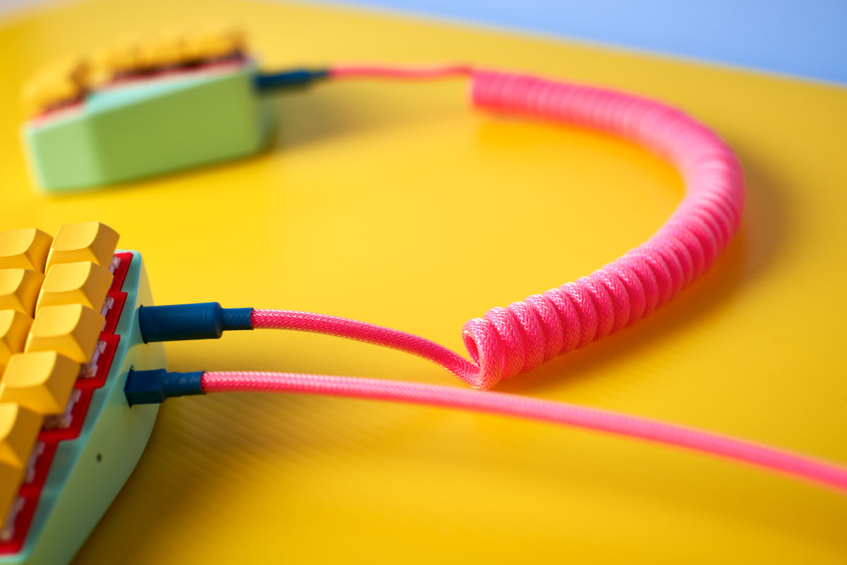
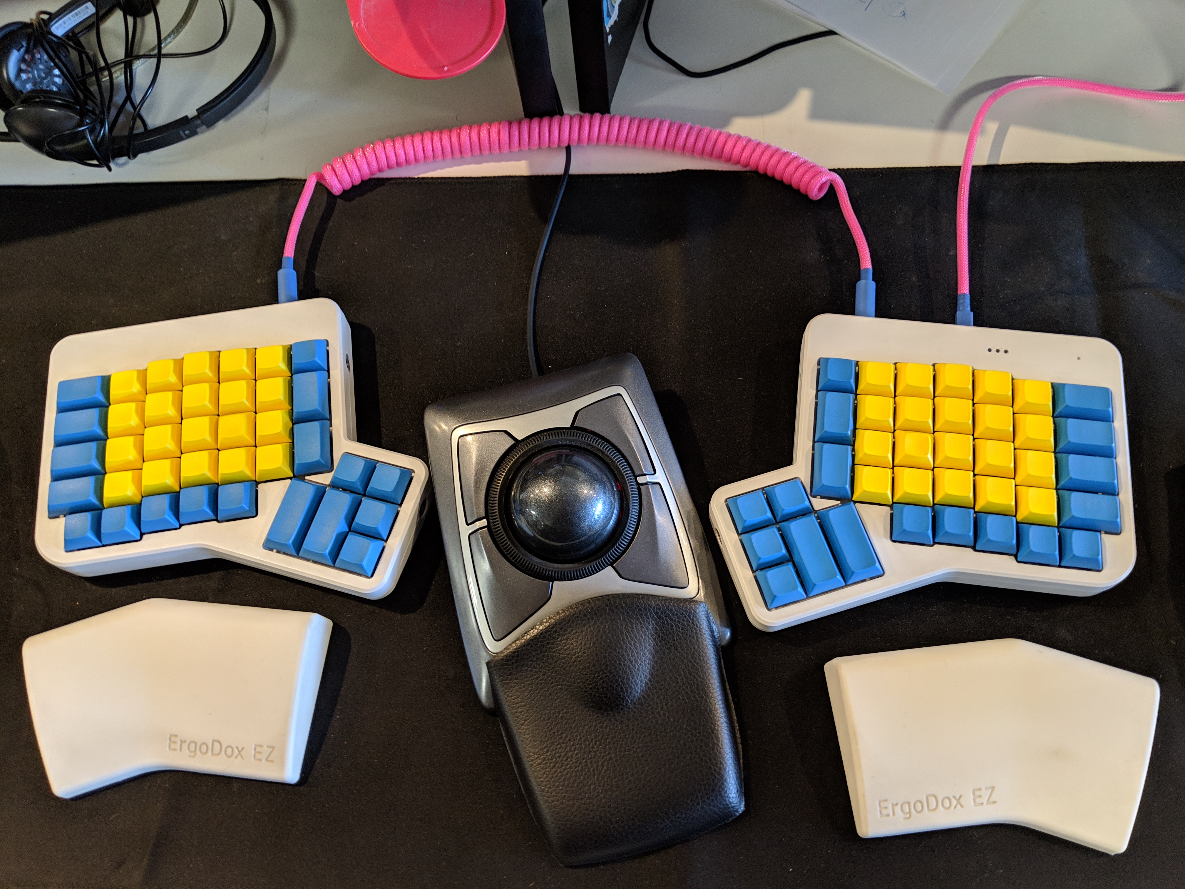
I’d been using the ErgoDox EZ for a couple of years, along with a regular mouse and a trackball mouse. I really liked a lot of things about the EZ. It had a split layout, along with column-staggered keys (vertically aligned), allowing for more comfortable wrist rotation. I used multiple thumb keys to switch layers, meaning I didn’t have to move my hands as much, improving accuracy and speed. Having a new layout encouraged me to learn to touch type “properly”. It was relatively easy to change the layout via the site confiurator (via which I went through over 20 revisions). And lastly, I thought it looked pretty weird and cool.
However, some things were slightly frustrating. I found it had too many buttons; after multiple keymap iterations, there were a bunch of keys that were unnecessary, which irked the OCD programmer part of my brain. I also noticed my typing accuracy still dropped, or performance slowed, when moving jumping my right hand to the mouse/trackball and back (not specific to the EZ). I found it also made a pingy noise when typing, however this probably could have been mitigated via modding.
I started looking around, and noticed on /r/MechanicalKeyboards that people were making all kinds of cool, custom keyboards. I realised it might not be as complicated as I thought to create exactly what I wanted. I’d also recently read Cal Newport’s “Digital Minimalism” which recommends trying to build something physical rather than digital. With all that in mind, I decided to try to keep what I loved about the EZ: a split ergonomic layout, however with fewer keys, an integrated trackball, and an ever odder look.
Keymap
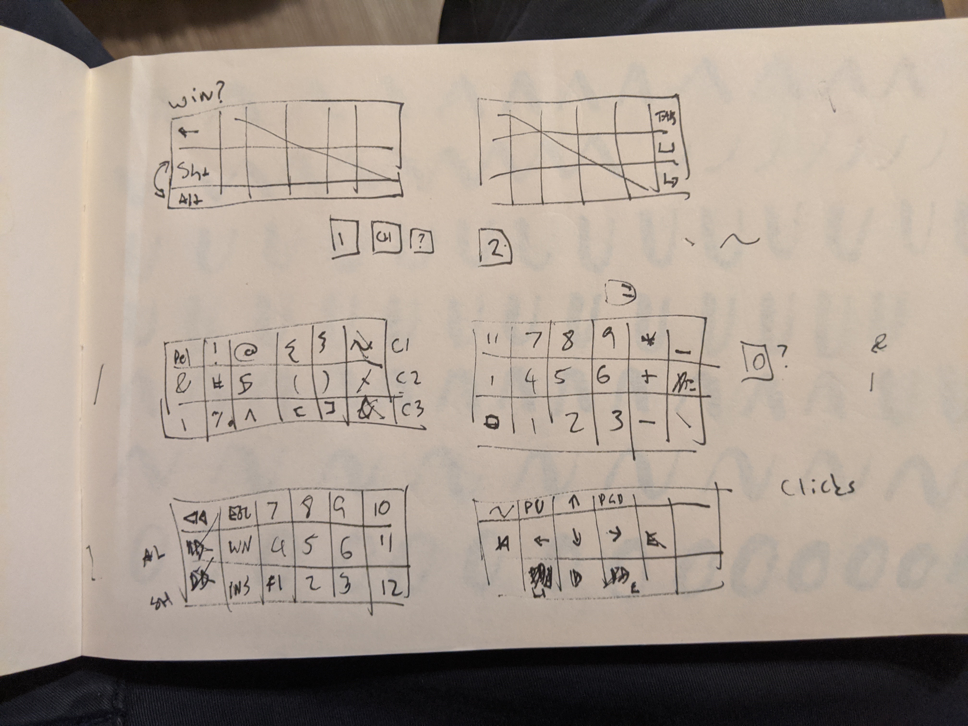
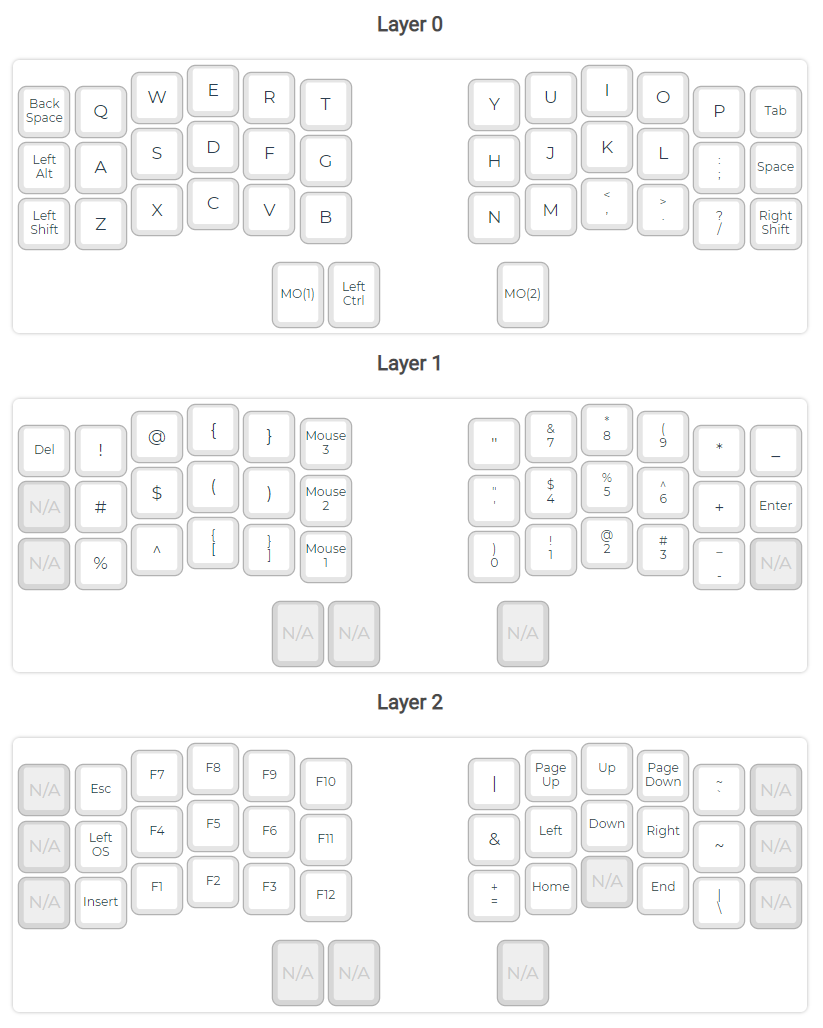
I decided to do all this while I was away at the beach for a few days with my family. Armed with only a pencil and some paper, I set to designing a relatively minimal keymap (I’m now aware that with stenography/chording you can take this even further!). I worked out the main key combinations. Over many pages. My wife probably thought I was crazed.
Scultping
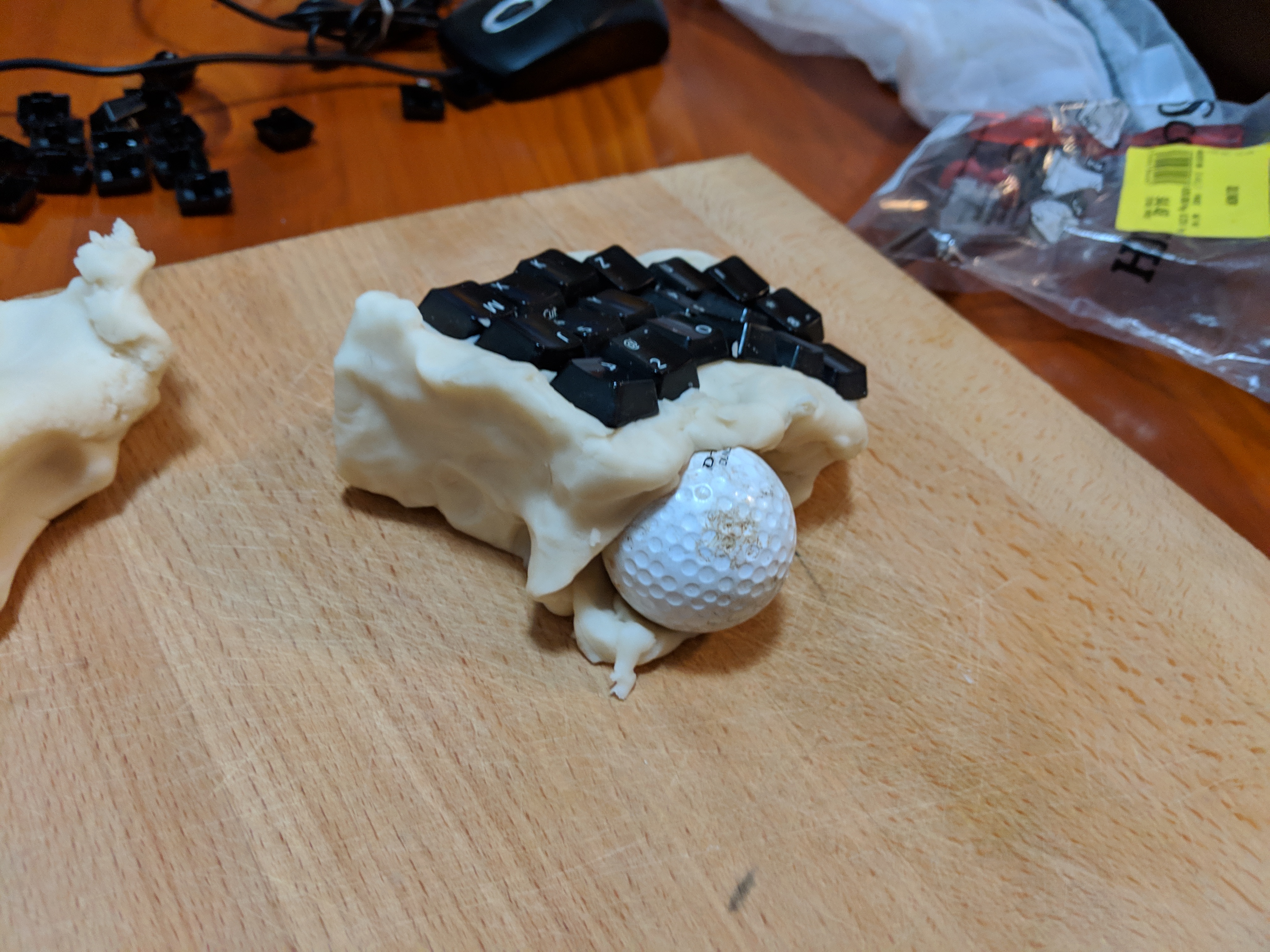
To start off with, I thought I’d try to find what was comfortable. I made some playdough, and started playing around with different shapes and angles.
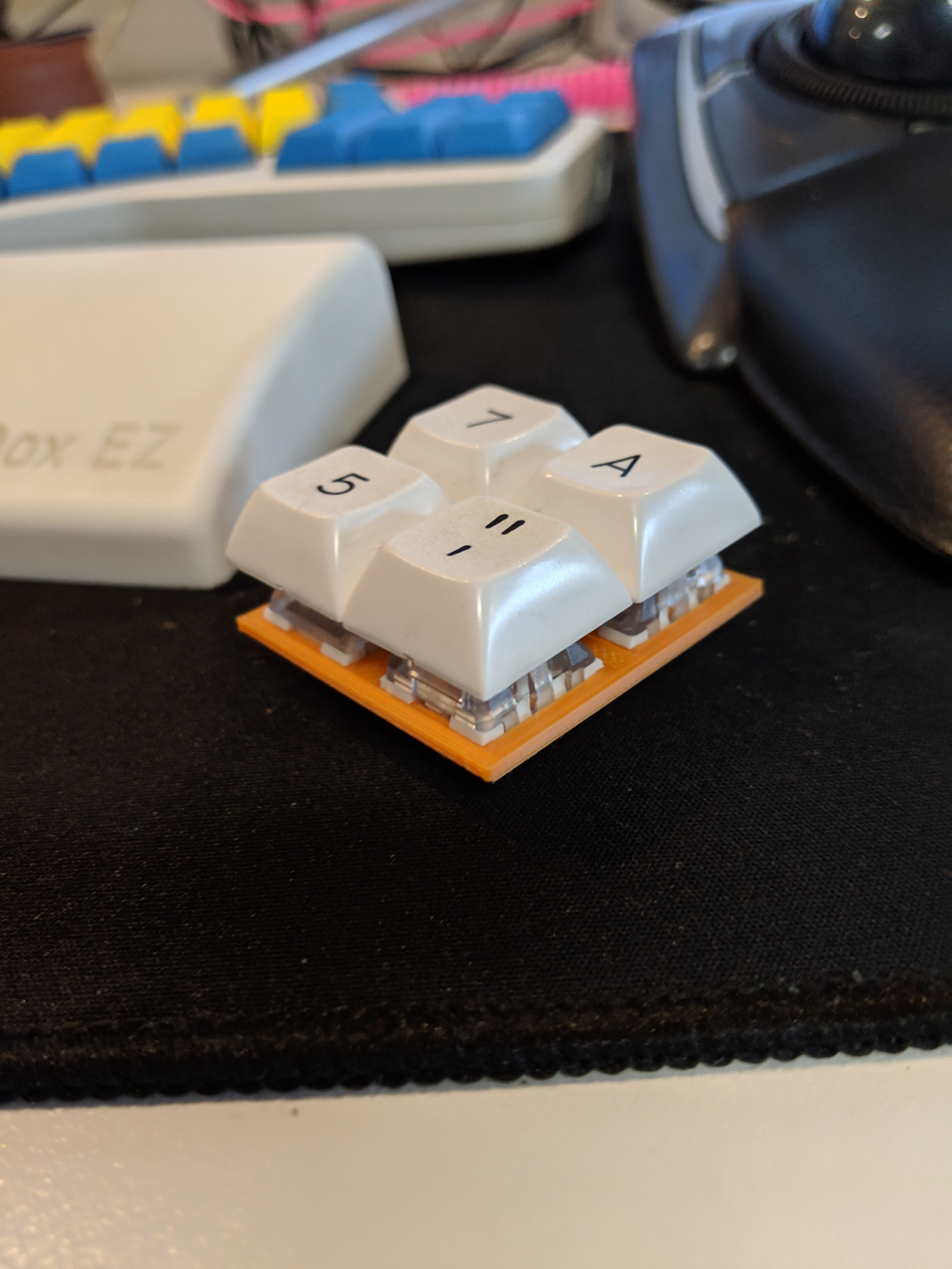
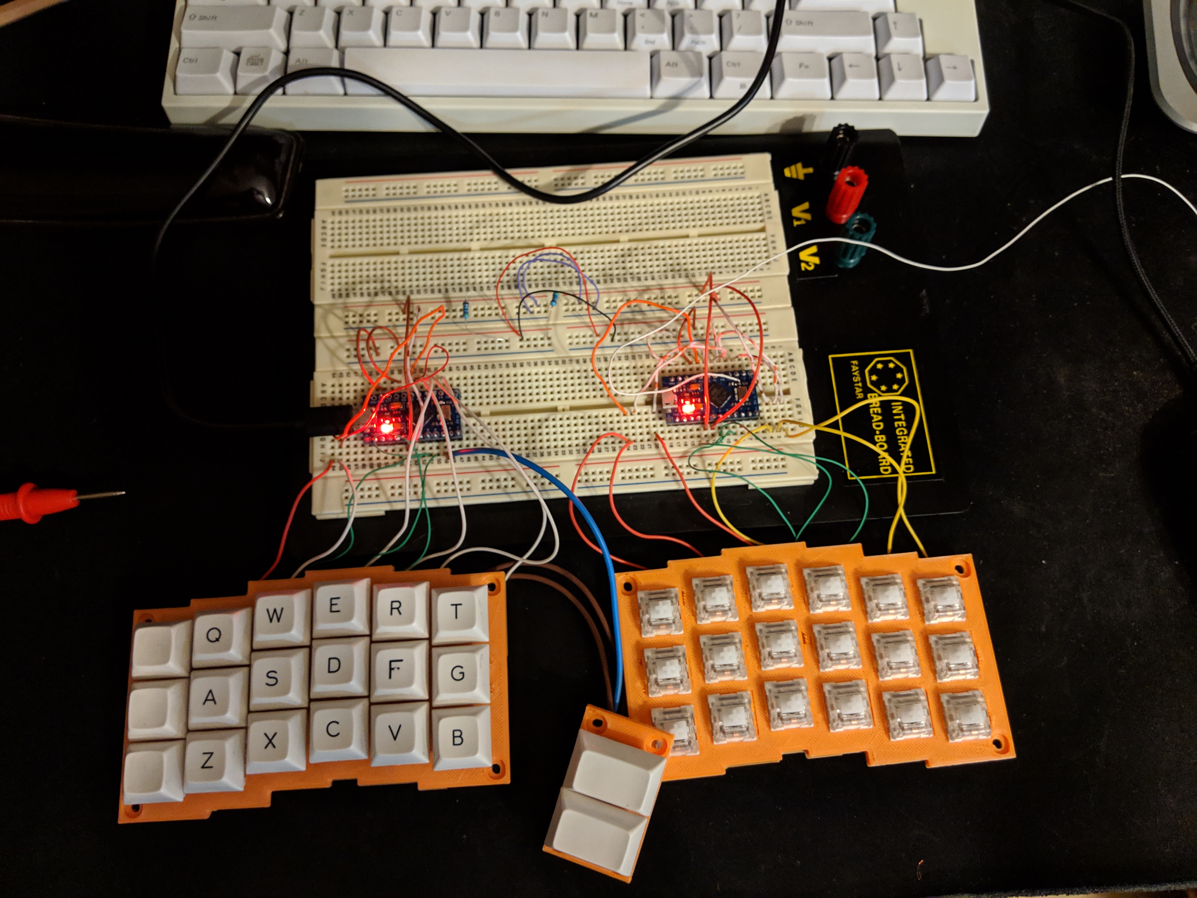
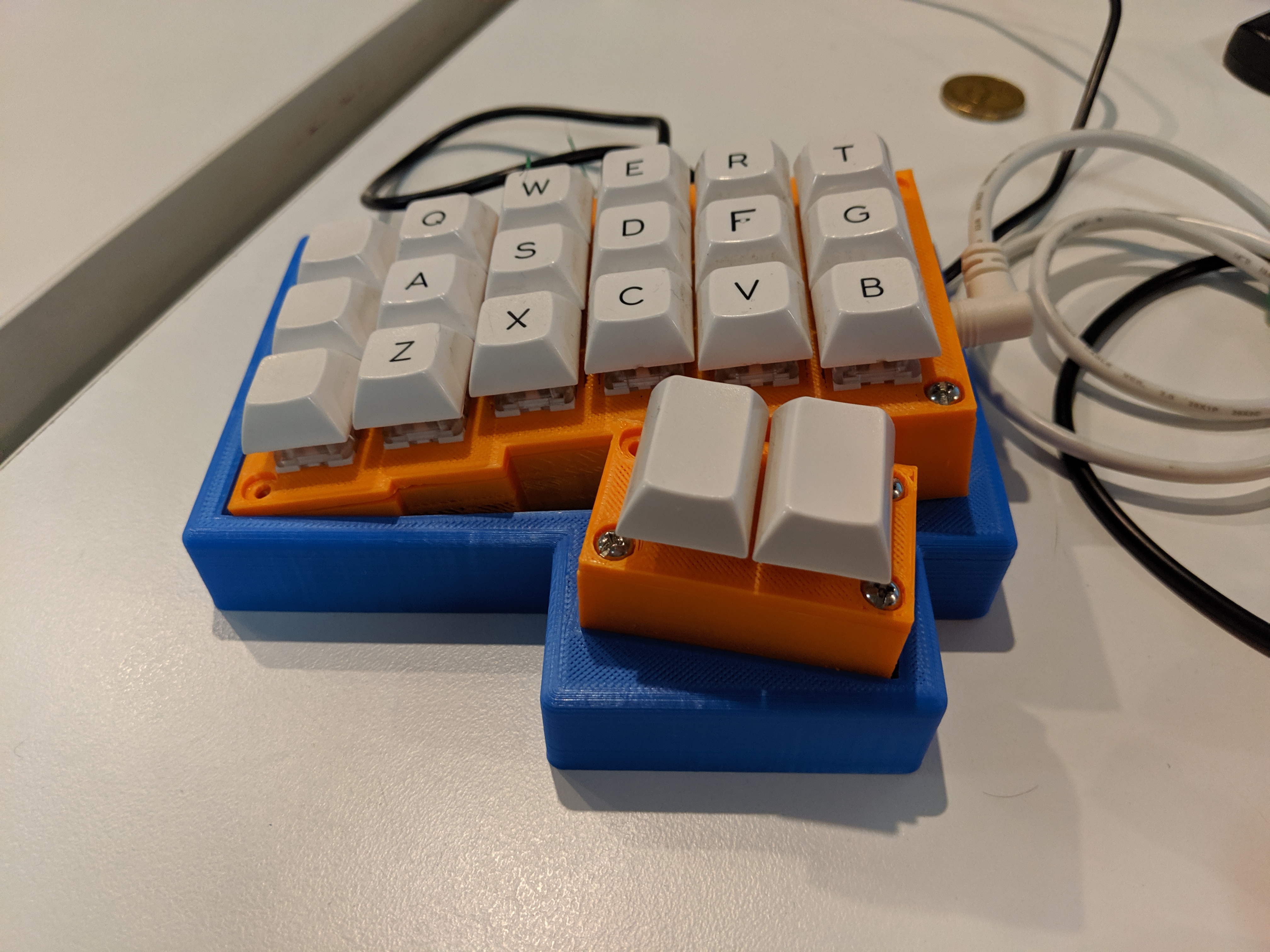
Handwire and initial print
Next up was getting something working to see if my layout was feasible. I ended up chipping in with a friend for a relatively low-end 3D printer, a Creality Ender 3. There was a lot of information around about handwiring a keyboard and using using QMK. I used the links on diimeep’s list or awesome split keyboards. I ended up making and using a handwired prototype for around 6 months before decomissioning it. I really liked the layout, but some of the connections were a bit flakey, leading to missed characters. It was very frustrating in that respect.
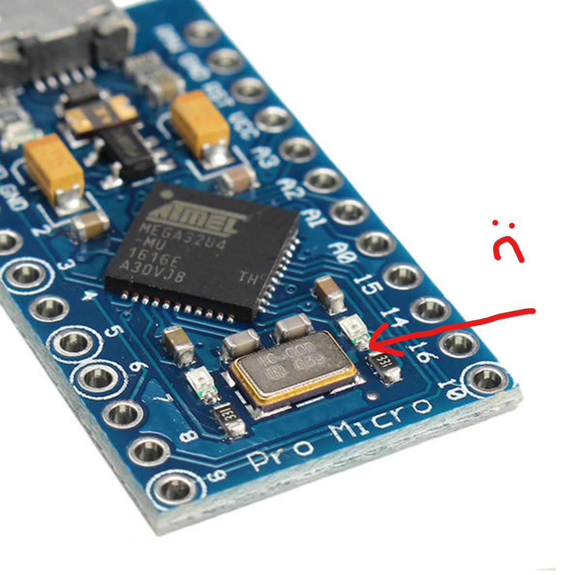
Tracking motion
I also had to figure out how to do a trackball. There didn’t seem to be too many ready-to-go options. One existing solution was to take apart an old PS/2 mouse, flip the sensor upside down, and put a trackball on top. I tried this, but it wasn’t very successful as the older optical sensors weren’t very good at picking up on the motion of my mini, plastic pool balls I’d decided to use for trackballs. It was also really hard to solder on to the Pro-Micro clock pad, which on this board was on the back of one of the LEDs.
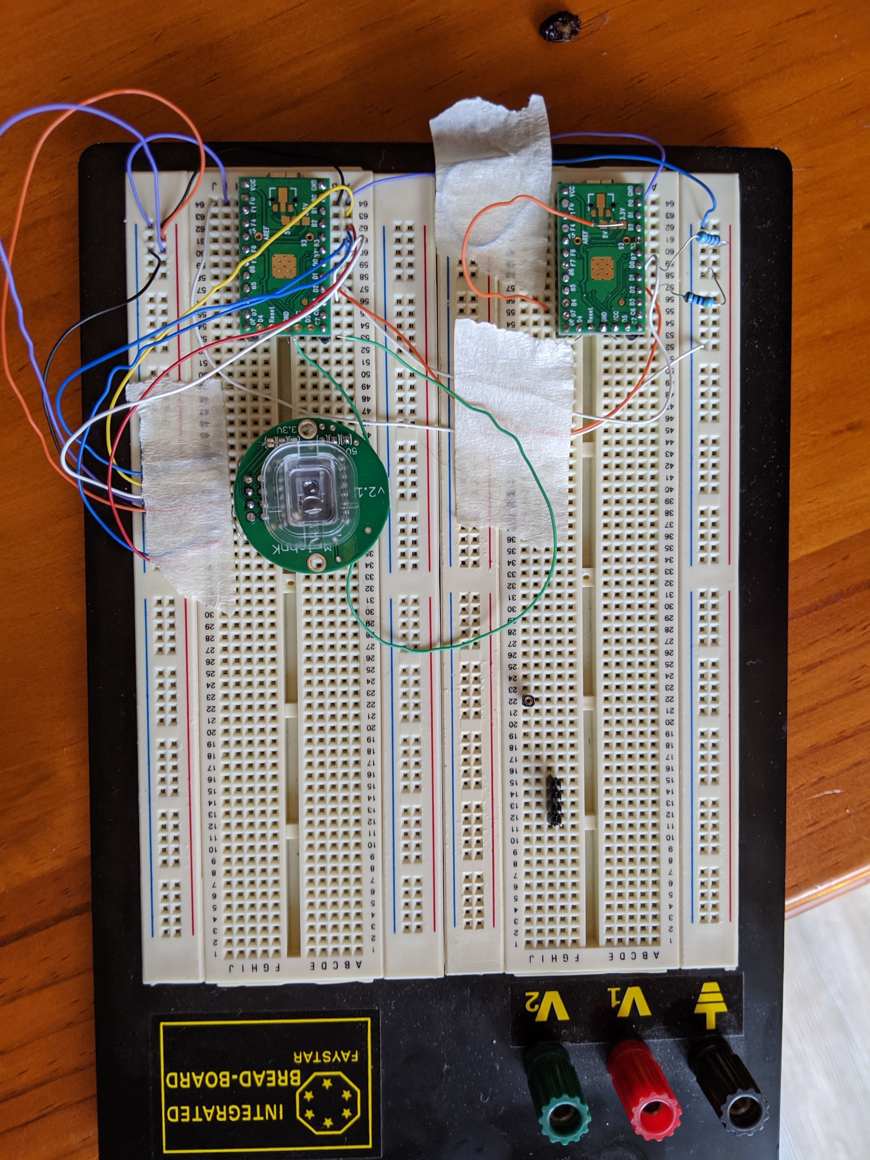
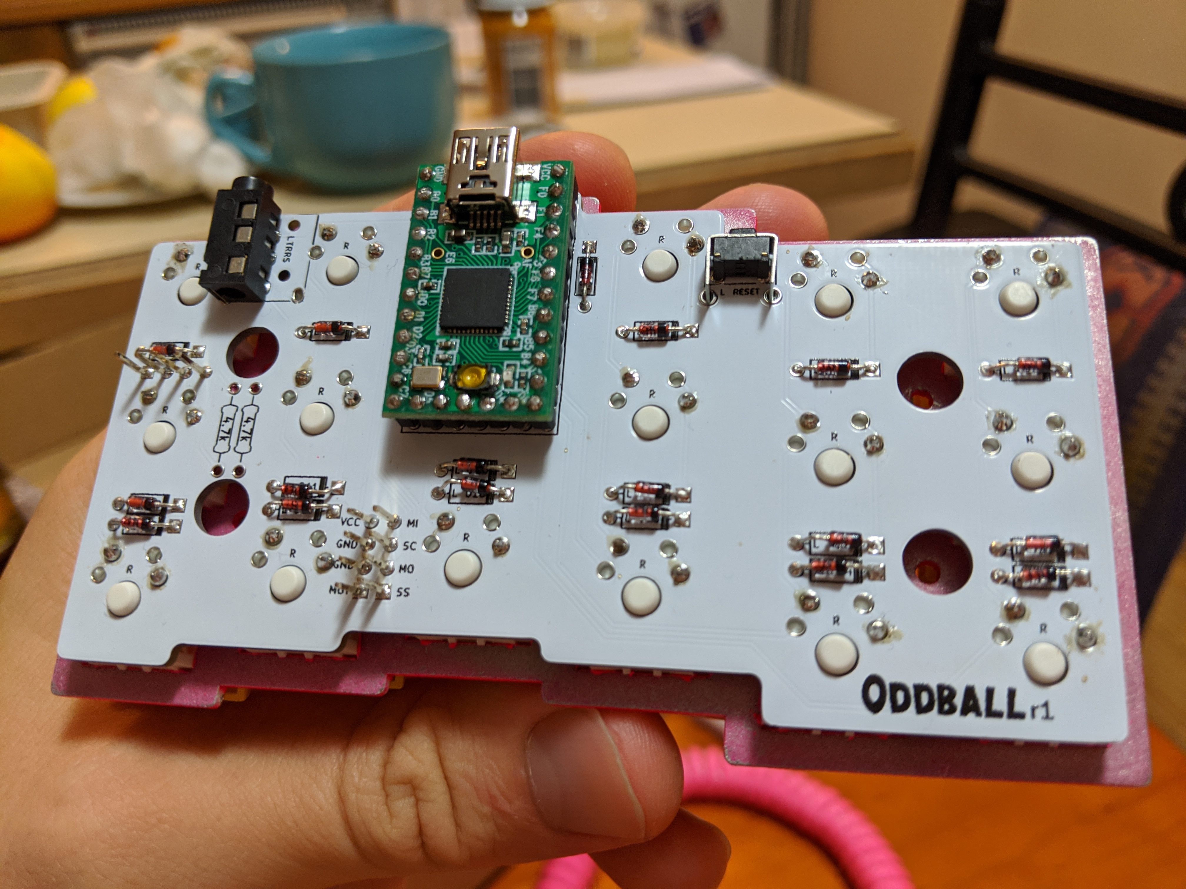
I had a look around for some alternatives. I settled on an ADNS9800 sensor. Intially I started to make my own design to house the sensor, but this was quite a steep learning curve for me. I ended up getting a board from JACK Enterprises on Tindie. I also switched to using Teensy 2.0s for controllers, as they have a breakout pin for the clock. Once the ADNS arrived in the mail, I soon got the Arduino sample code working, tracking motion. It was a start. It took a lot longer to get things working with the Teensy, running QMK, communicating with the sensor, although not as long as I feared. I was pretty stoked when I finally got it all working, as I couldn’t really find anyone else (at the time) who had it working, so it could have been a showstopper!
Case/plate design
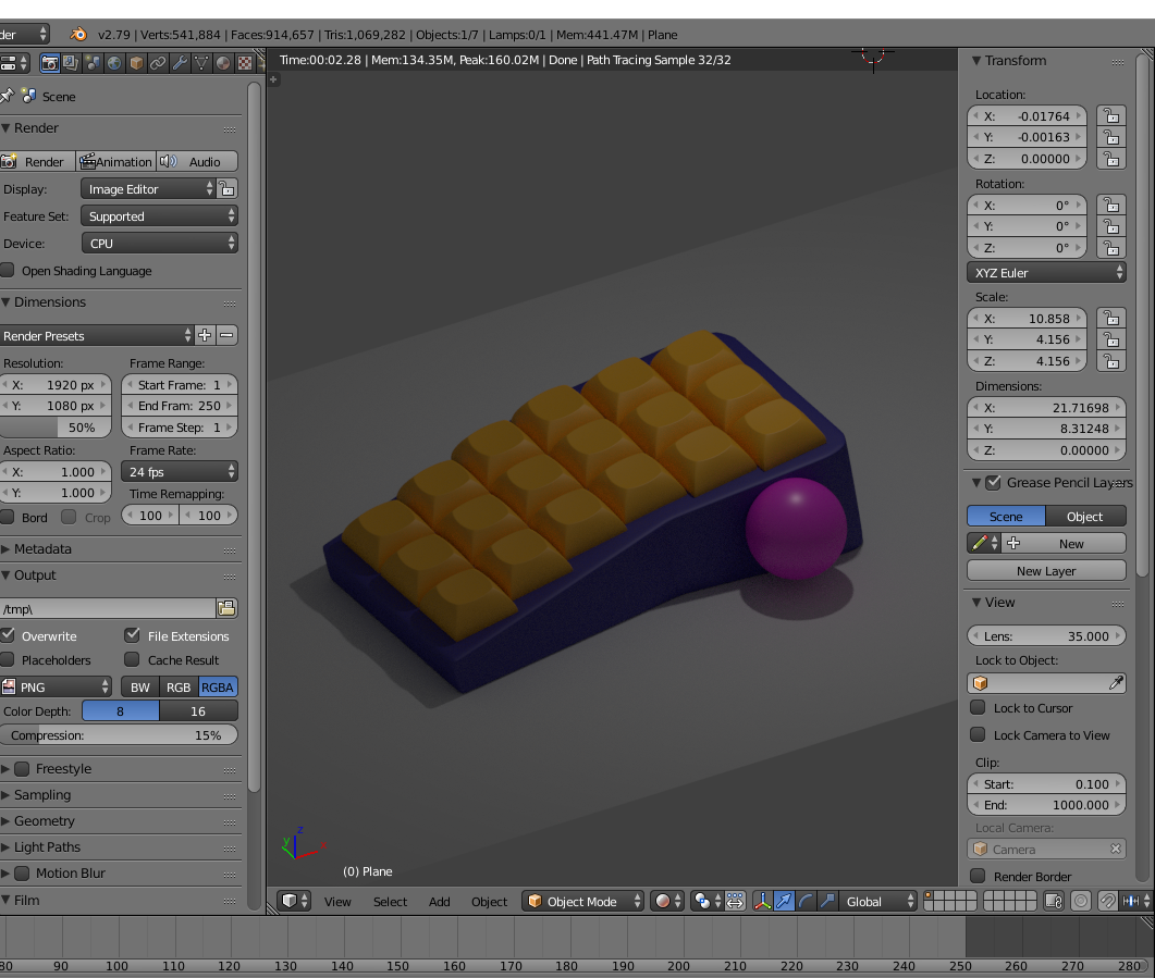
Blender
I’d used Maya, a 3D rendering package, in uni, so I thought I’d try out a free alternative: Blender. I had a play around, learnt the basics, and made a rough draft. However, I quickly came across some limits, or rather some friction, when dealing with technical designs in Blender. While you can stack modifiers on top of each other, it’s hard to parameterise everything. So I started to look into other options.
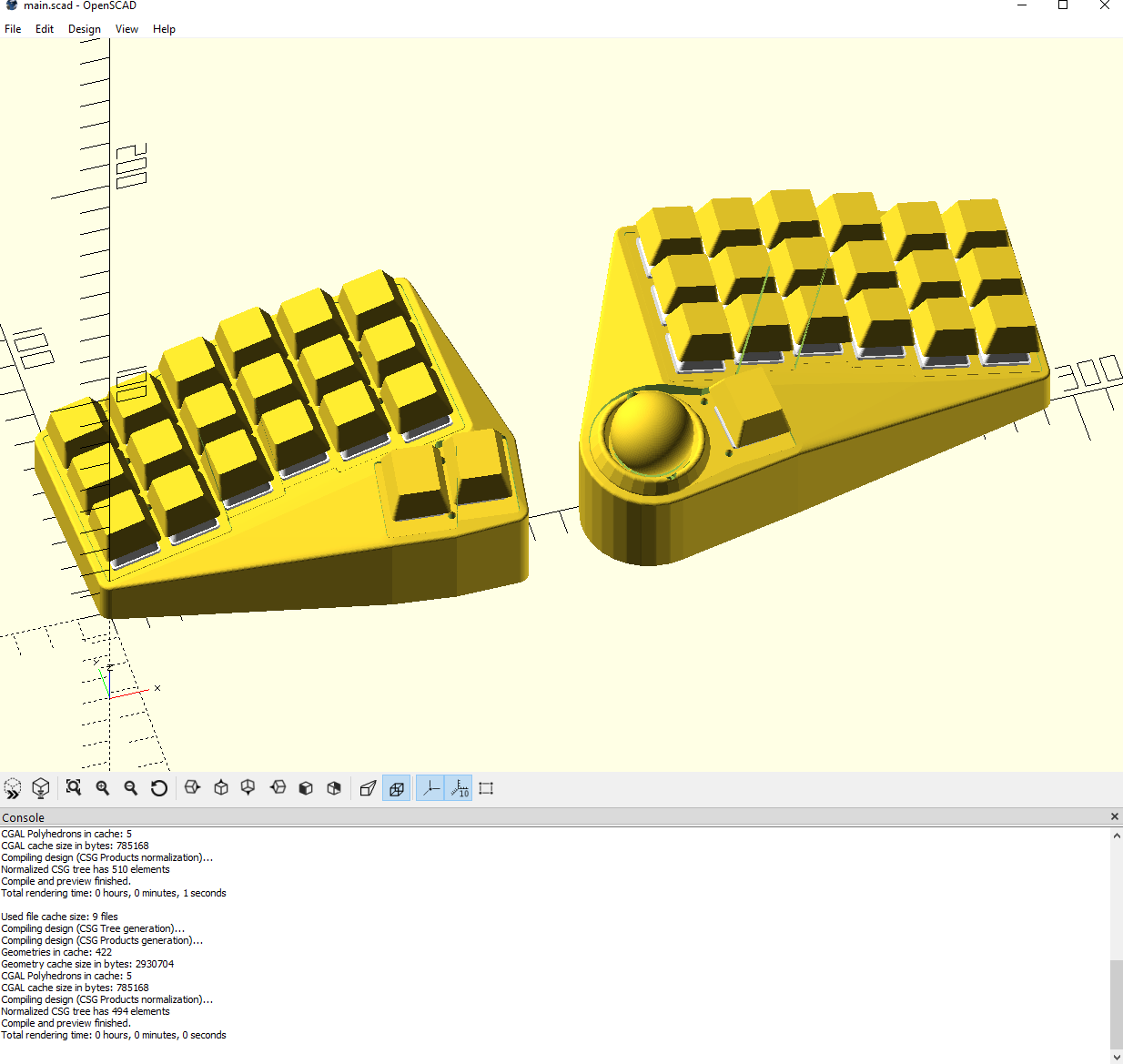
OpenSCAD
I looked thought a few options, and settled on OpenSCAD, which allows you to code the whole your whole design, and tweak values wherever you want. This was also a relatively easy learning curve for me as programmer, and works pretty nicely with source control as a bonus. It took a while, but eventually I had my plates, case and PCB outline modelled.
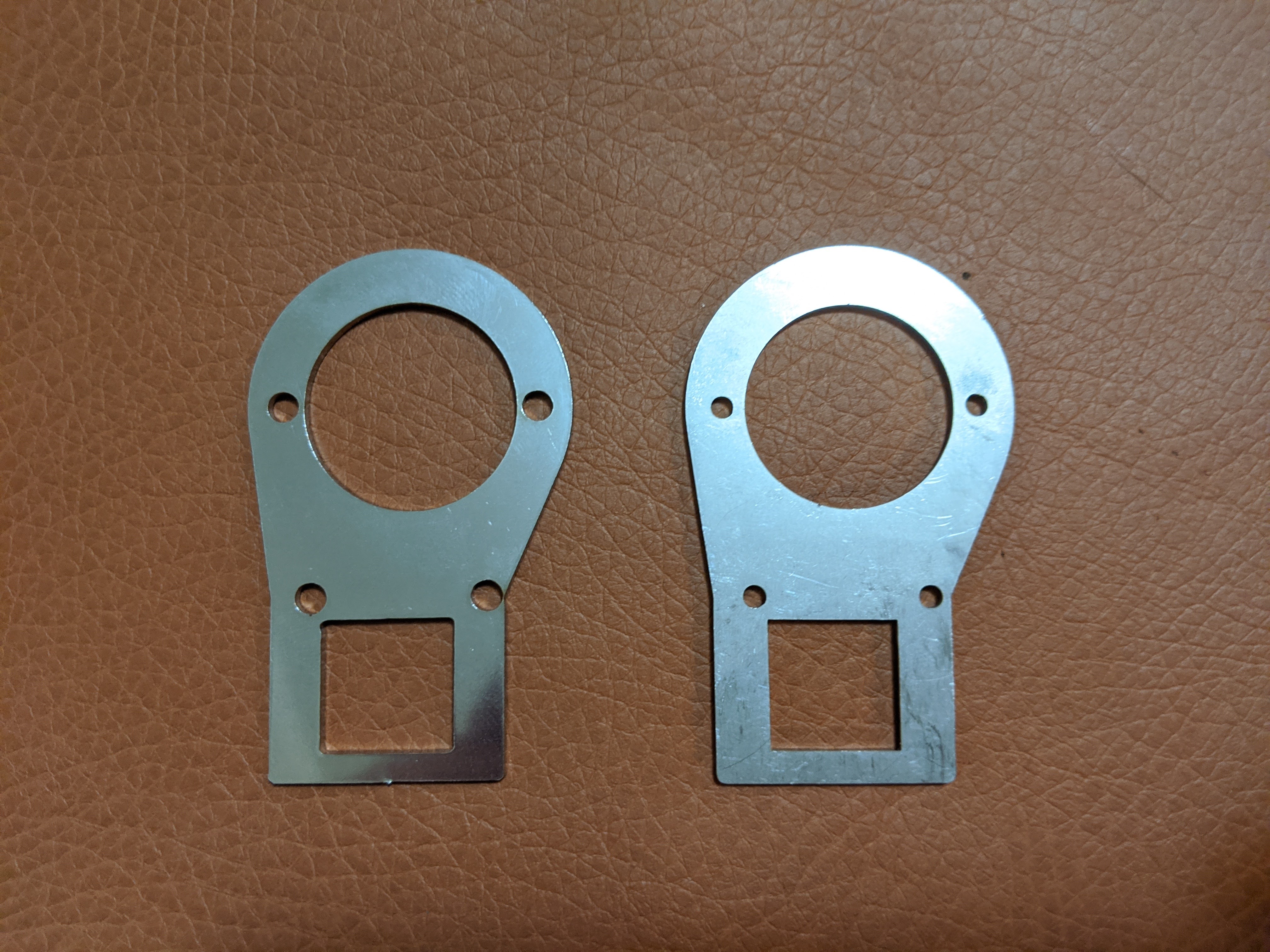
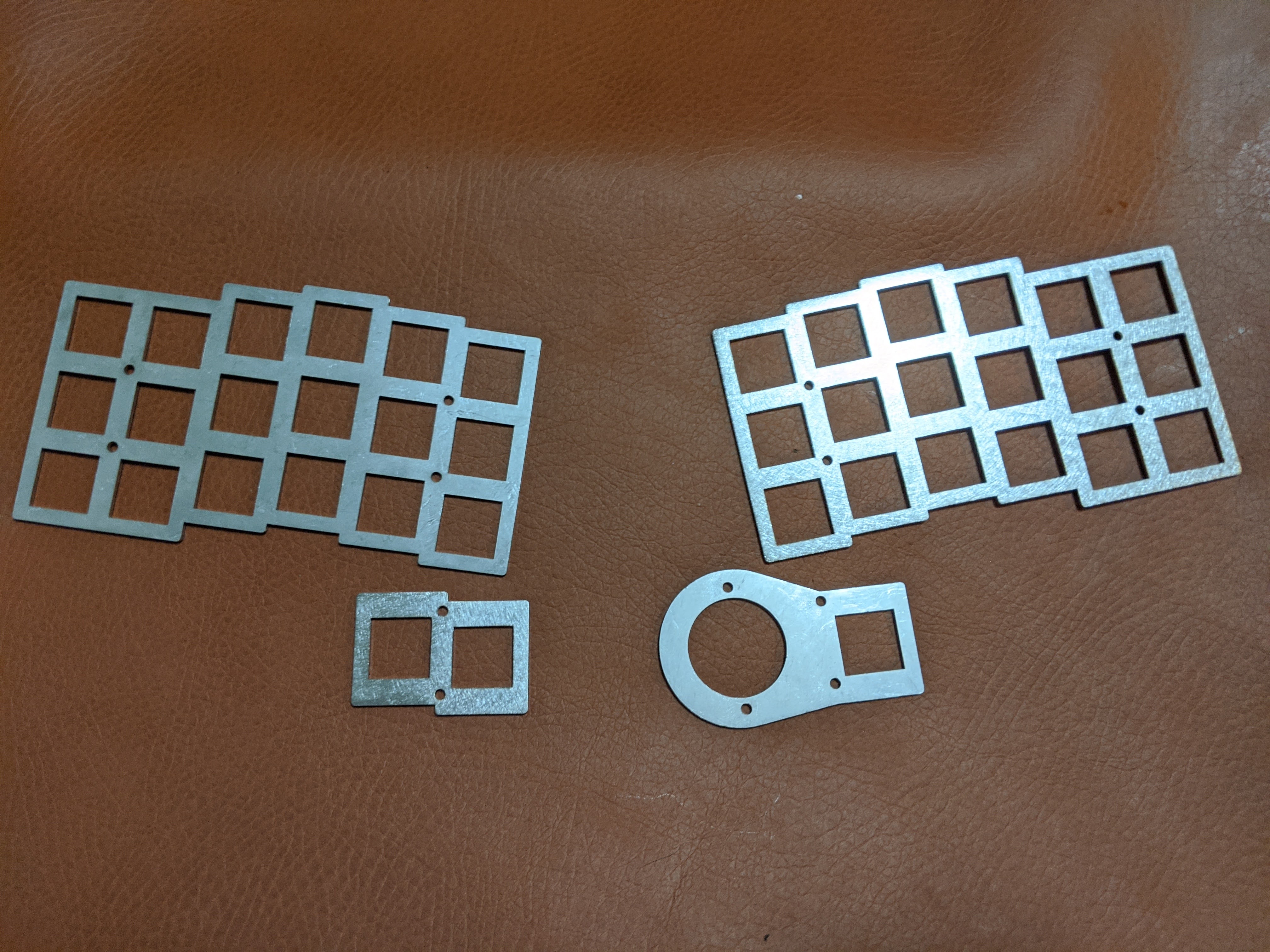
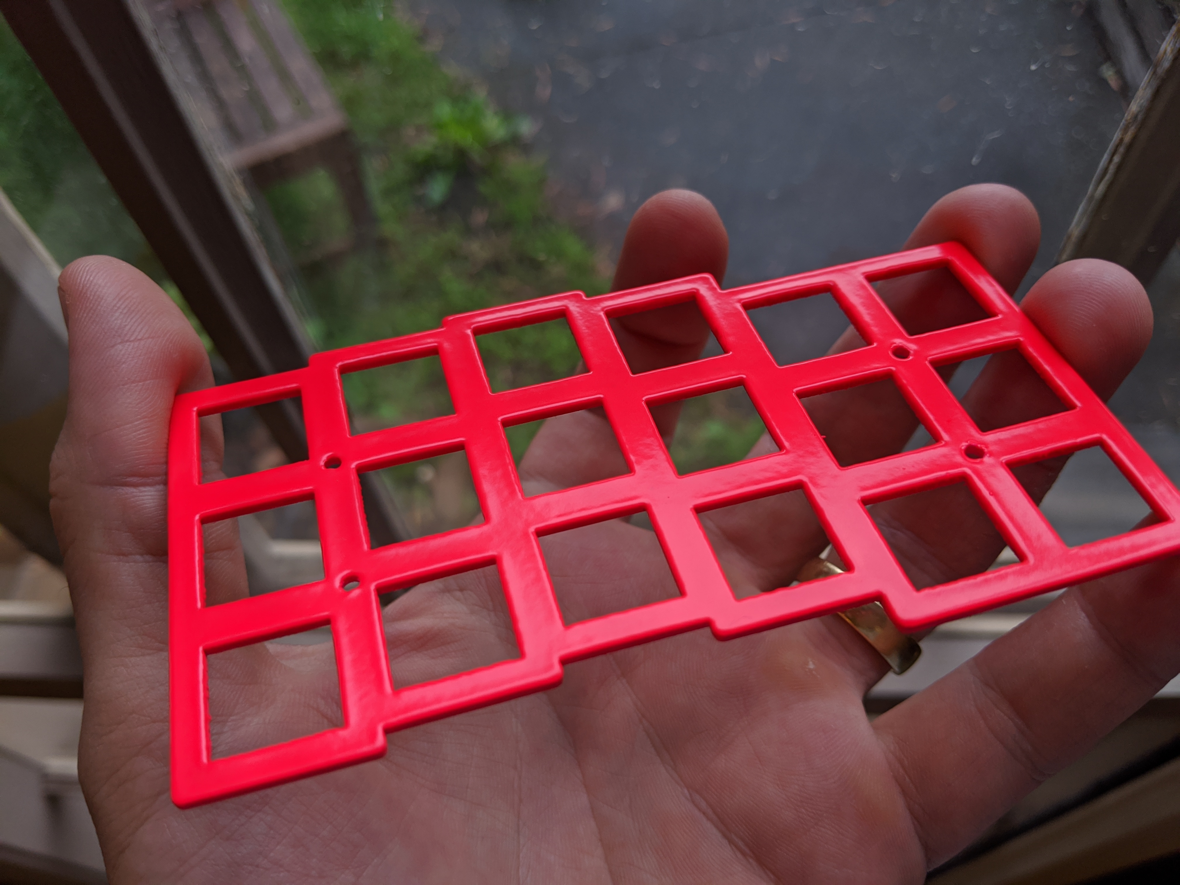
Plates
I generated my plate files, two per hand and two per thumb, which I’d decided to get laser cut in 1.5mm steel. I looked at a few services, and sent off the right thumb piece to Lasergist for an initial test. While waiting for it’s delievery, I found LaserBoost (note, not Lasergist) took direct .dxf files which made things a little easier. I’d just allocated a bit of extra money so I just sent it all off to LaserBoost. Comparing the experience, I found Lasergist to be a little slow, although to be fair it was in the middle of the Christmas break. I also found LaserBoost to have neater cuts, and also allow for higher precision on designs (LaserBoost min. hole diameter 1.5mm on 1.5mm thick steel, whereas Lasergist is 3.0mm).
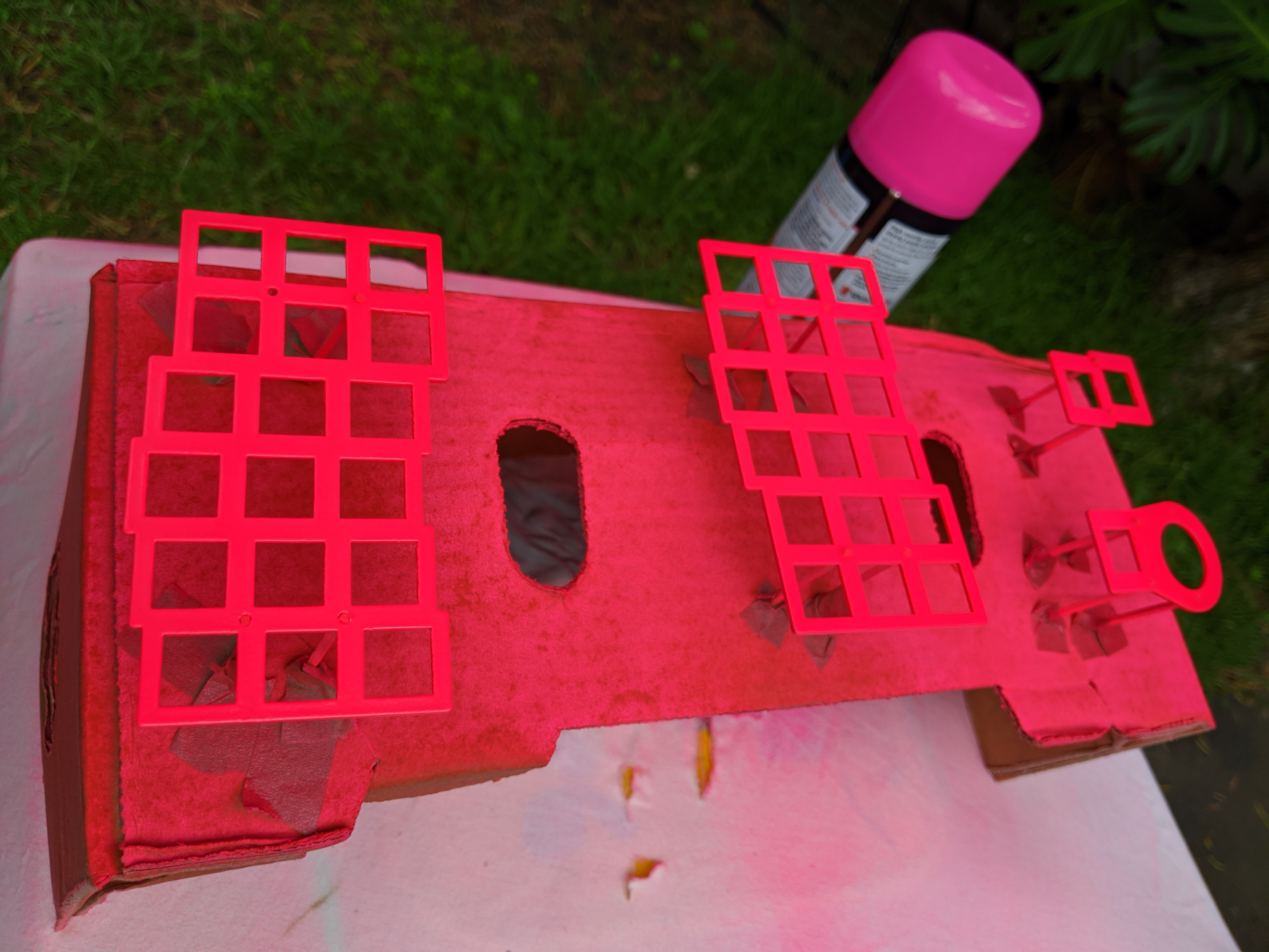
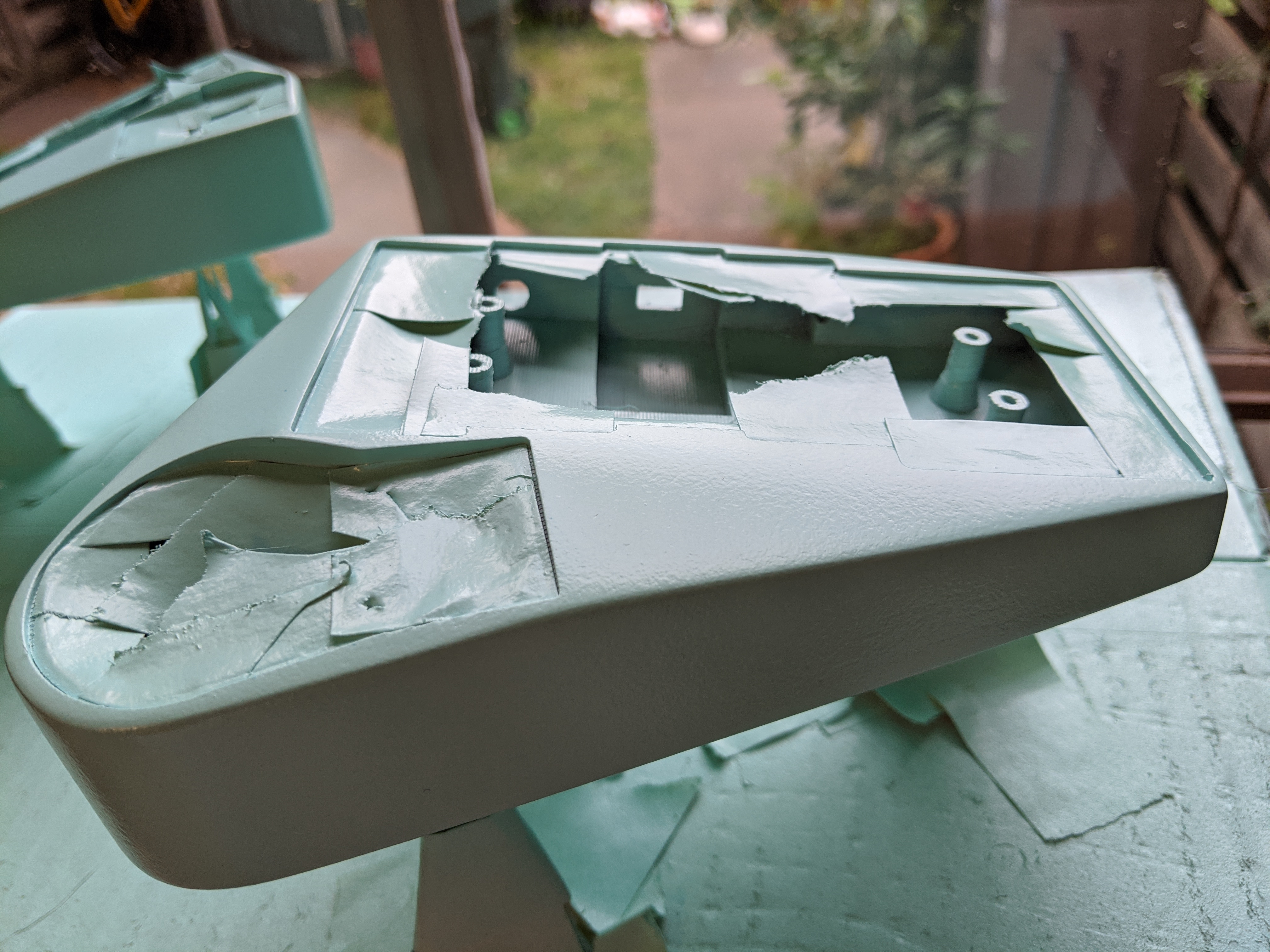
As my plates were going to be exposed in the case design, I also decided to paint them. I used a couple coats of primer, a couple of neon pink, and a clear satin coat to finish. It came out great, however I stored them a little prematurely, causing some blemishes on the still-wet paint.
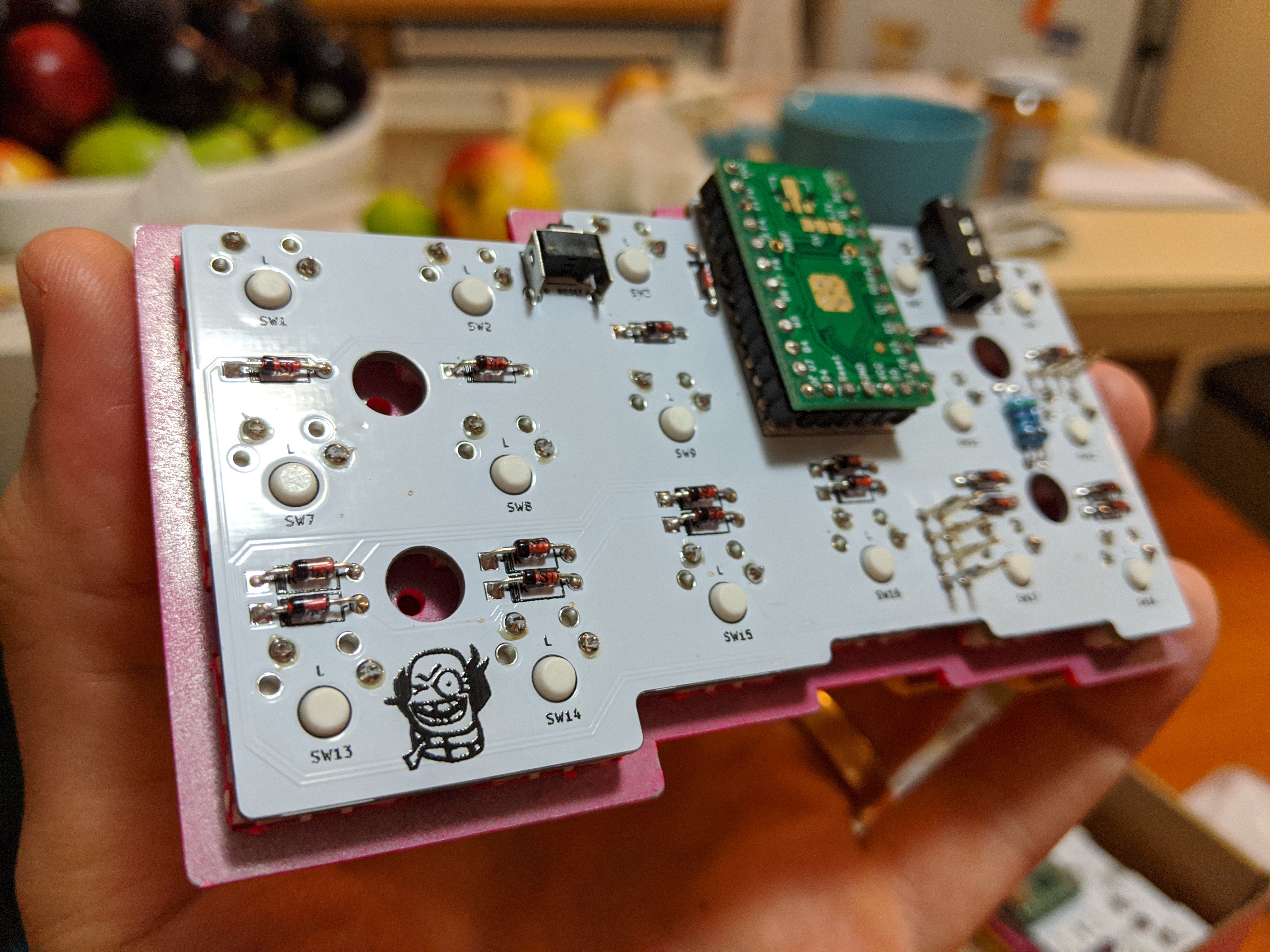
PCB
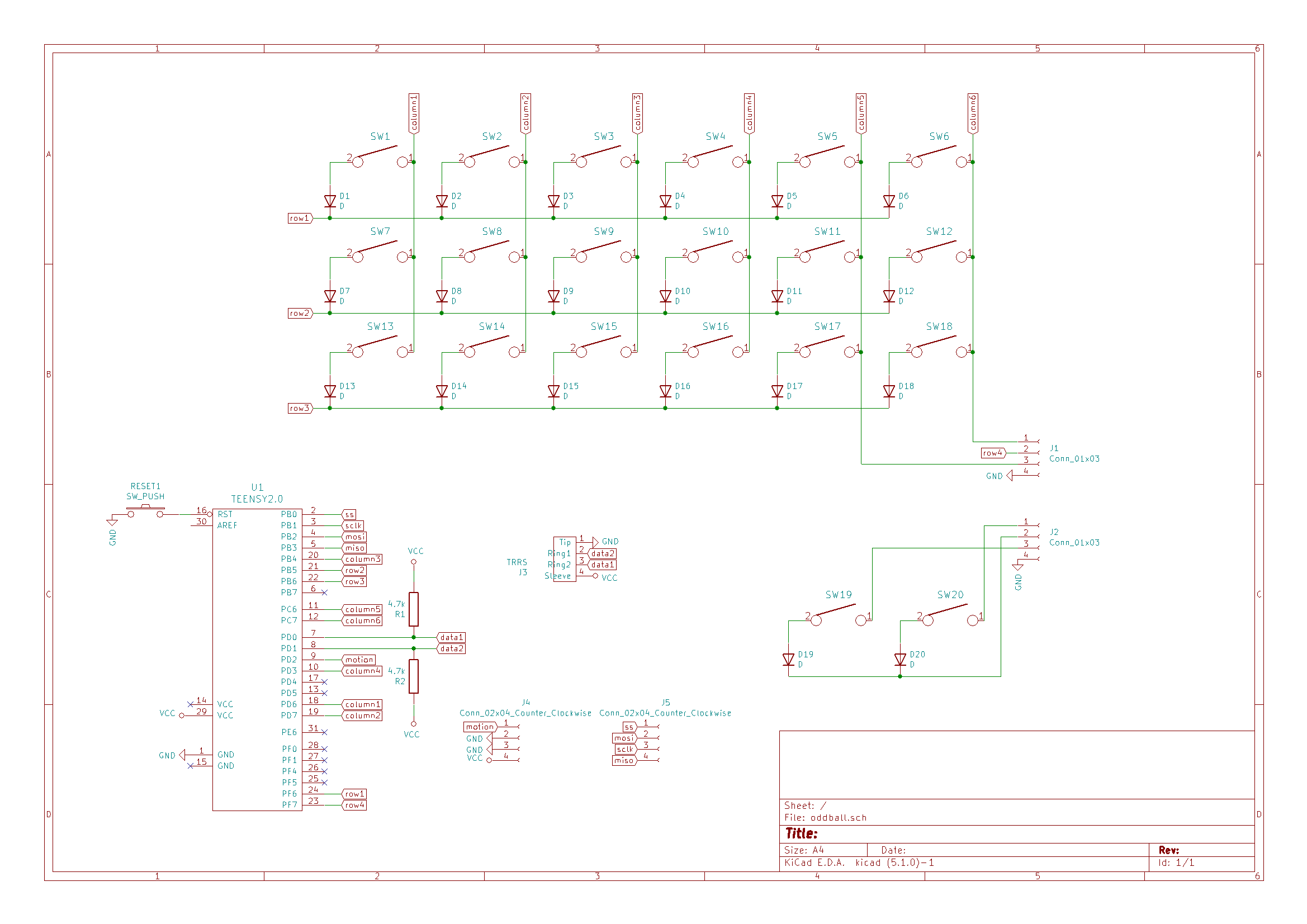
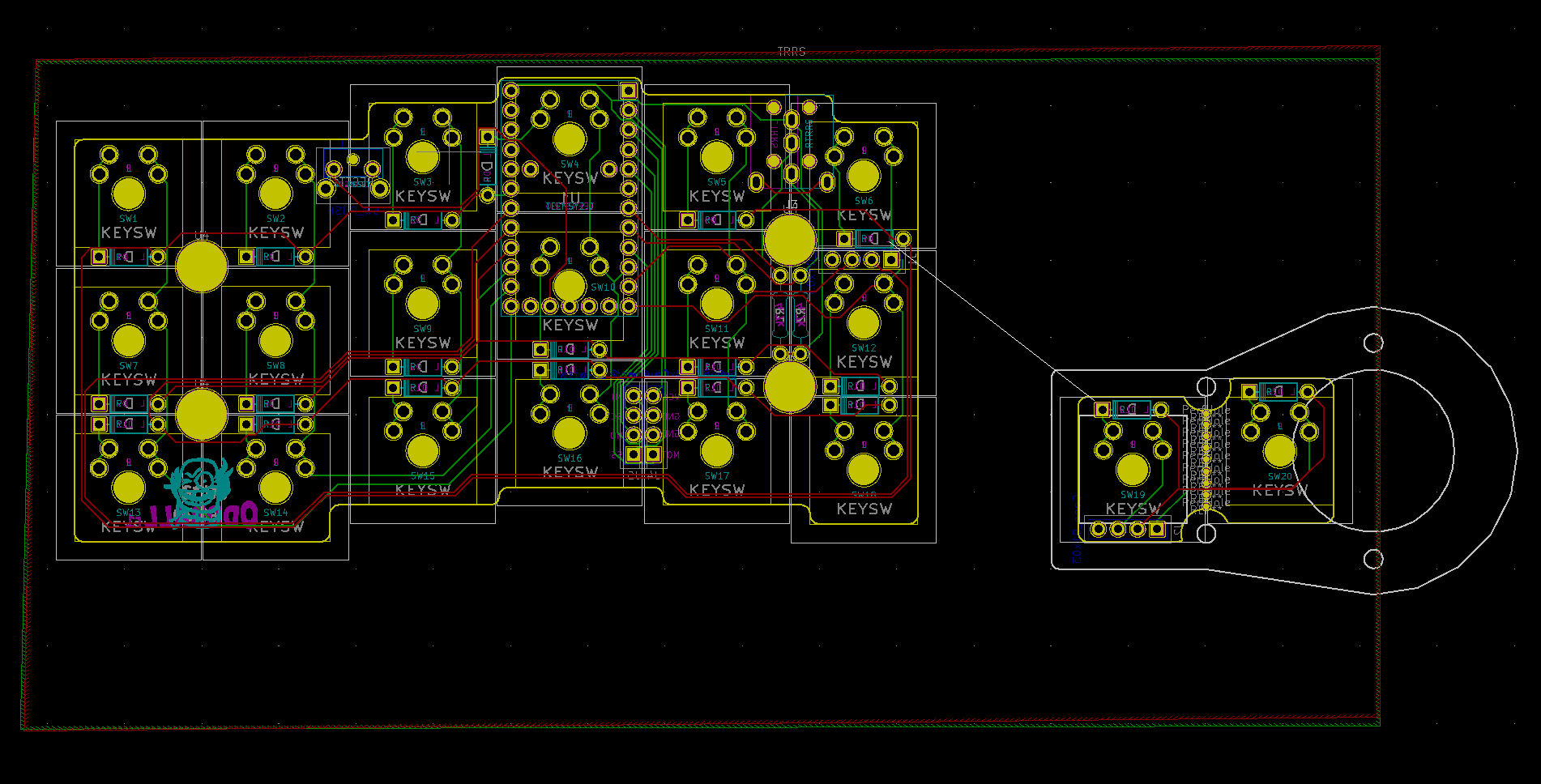
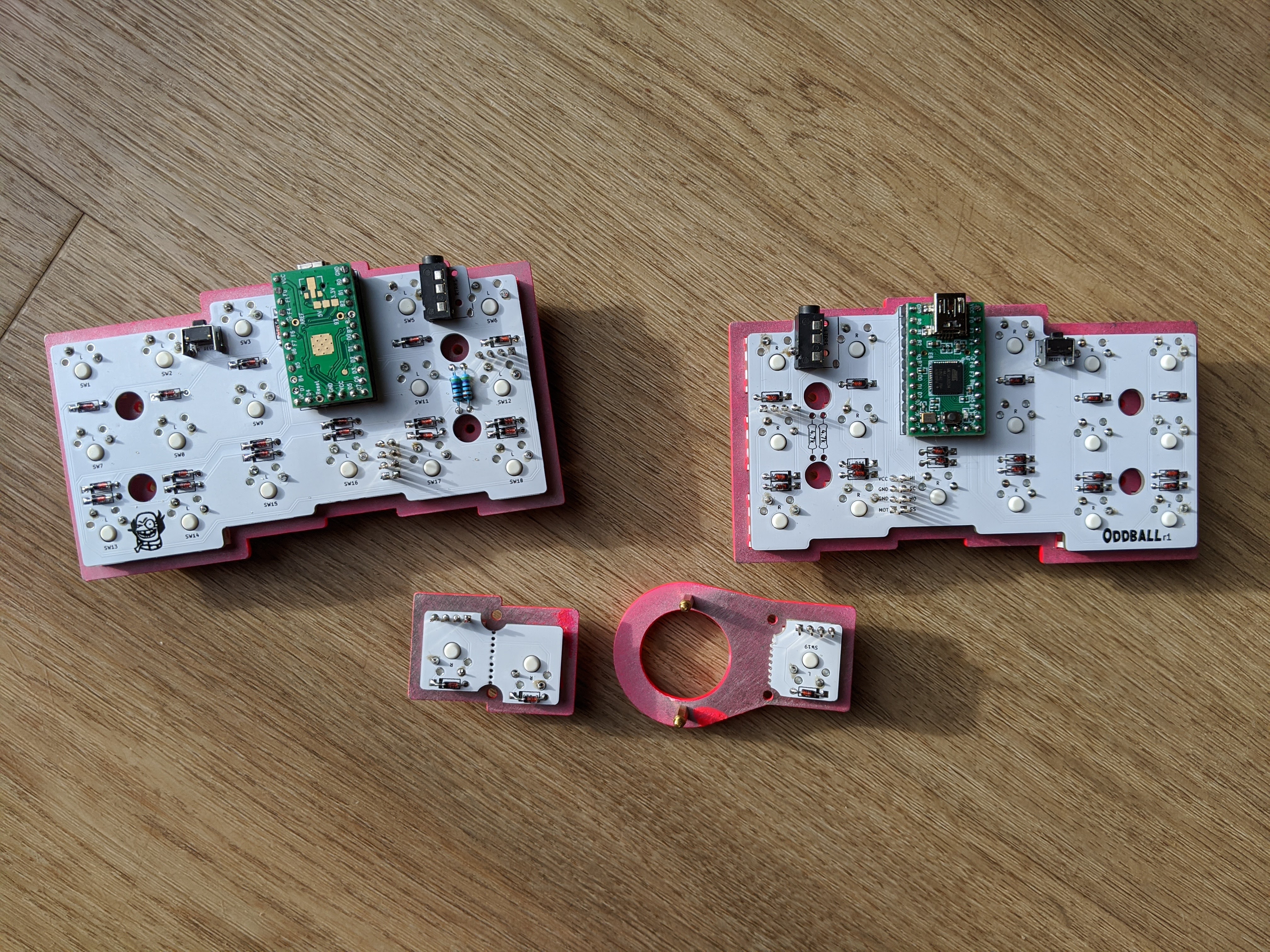
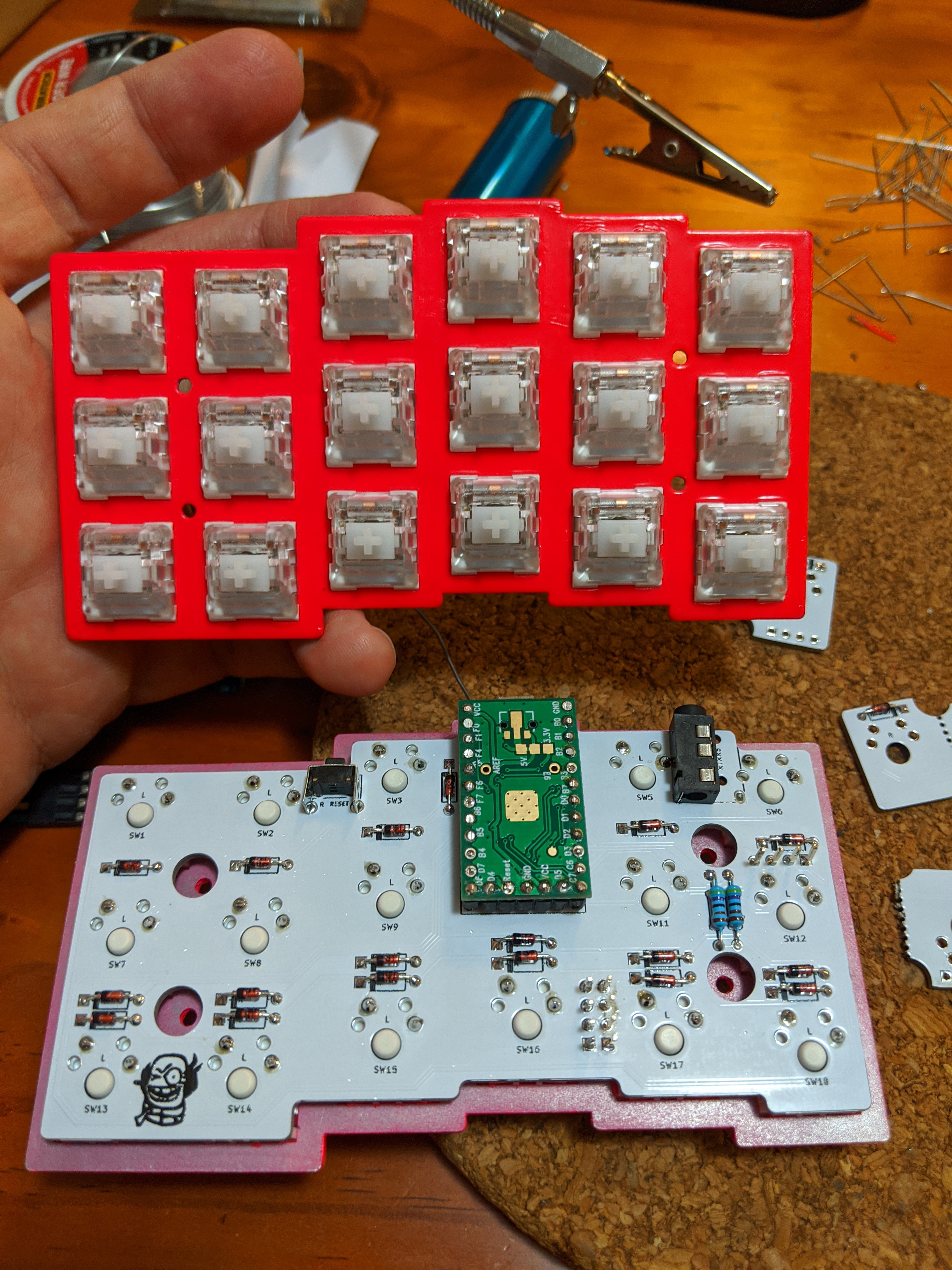
I didn’t want a repeat of my dodgy, flakey handwire. I thought it would also be nice to have something reproducible, plus I’d also partly started to endeaver to learn new things. So I decided to design my on PCB (printed circuit board). To save money, I’d try to make the thing reversible, so the same PCB could be used for both left and right sides. Drawing on many community resources, eventually I had my PCB design done in KiCad. Unsurprisingly, it turned out to be a lot more work than I had anticipated.
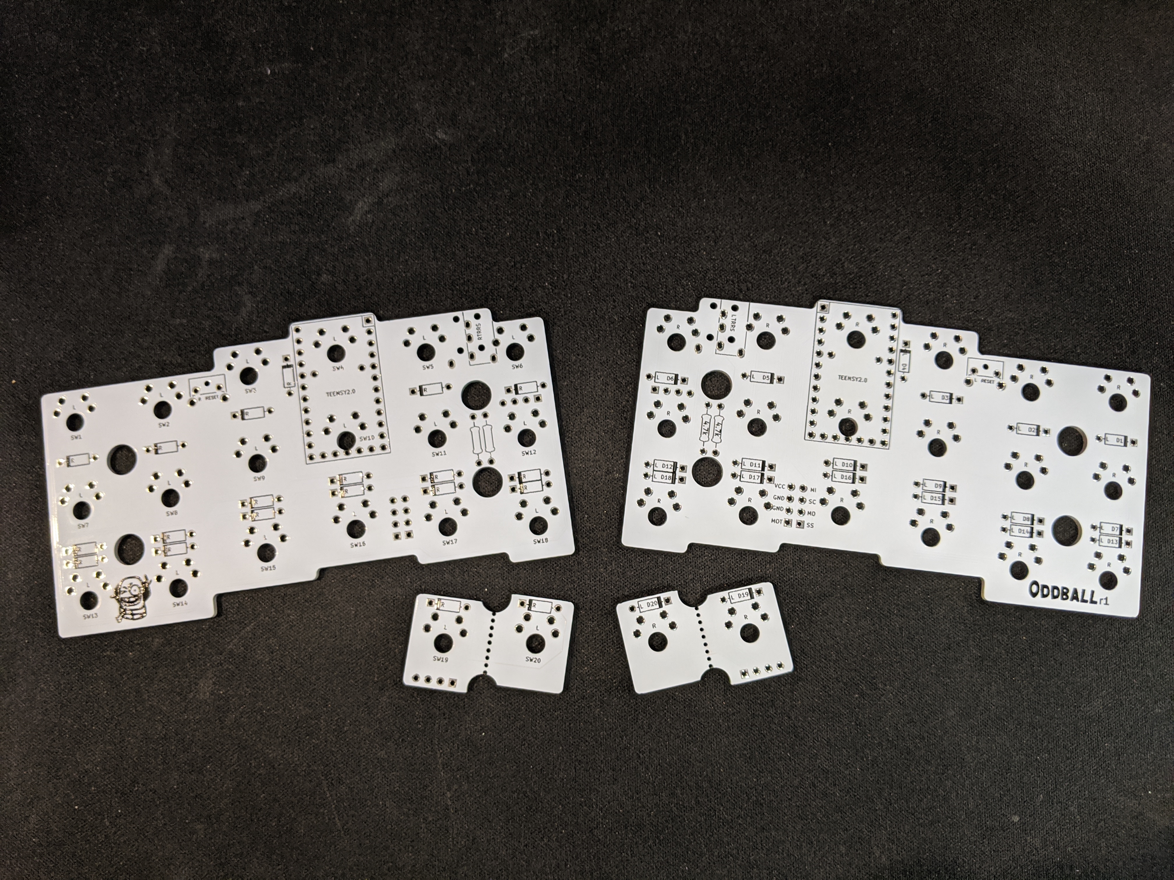
For manufacturing, I ended up going with JLCPCB, a Chinese PCB manufacturor with really cheap prices. I was really happy with the result. I orded during Chinese New Year (2020), so COVID-19 was just starting to hit. At the time of writing a lot is still unknown about the virus, but I definitely wouldn’t be expecting any international deliveries to arrive promptly.

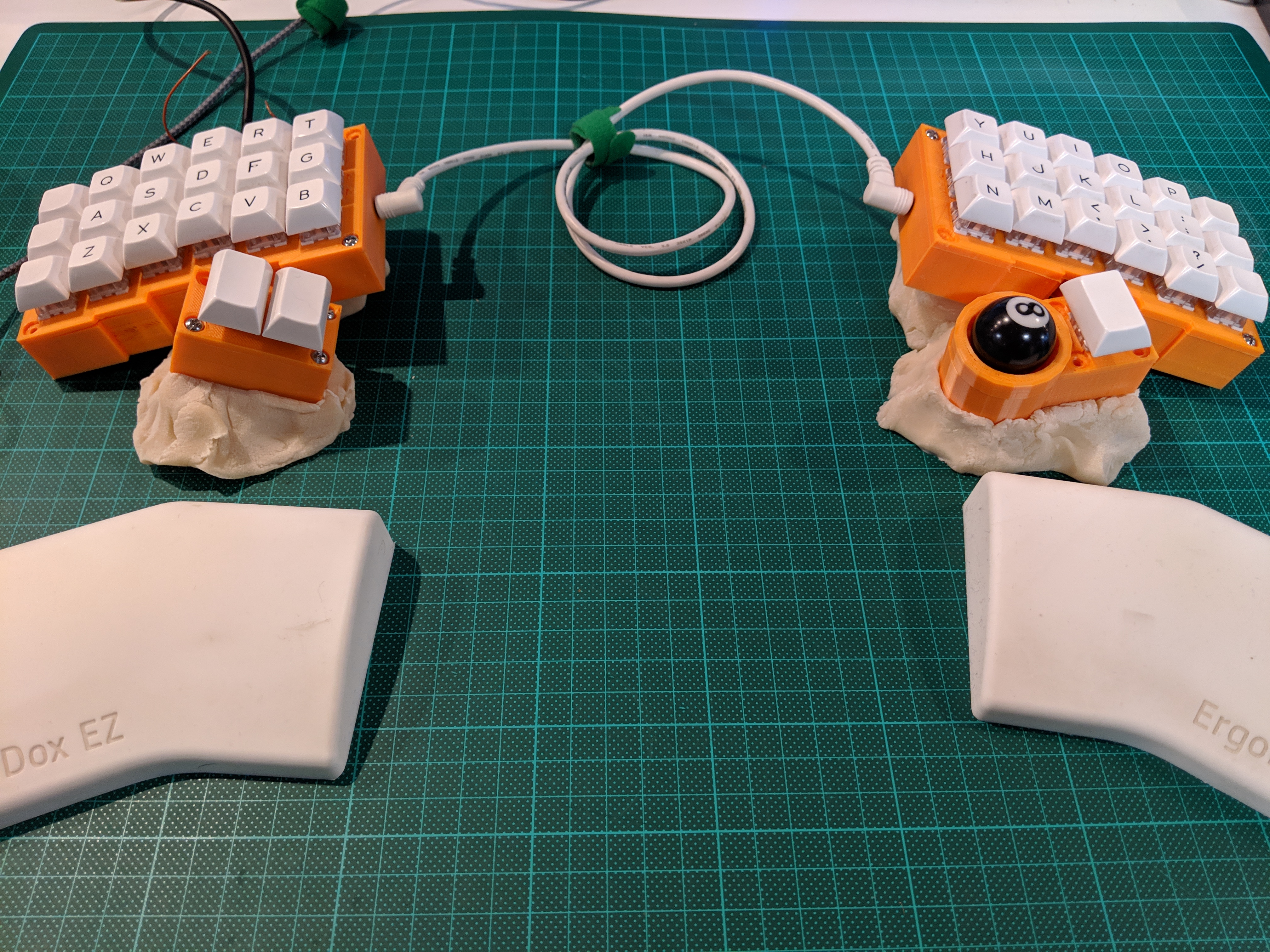
Final thoughts
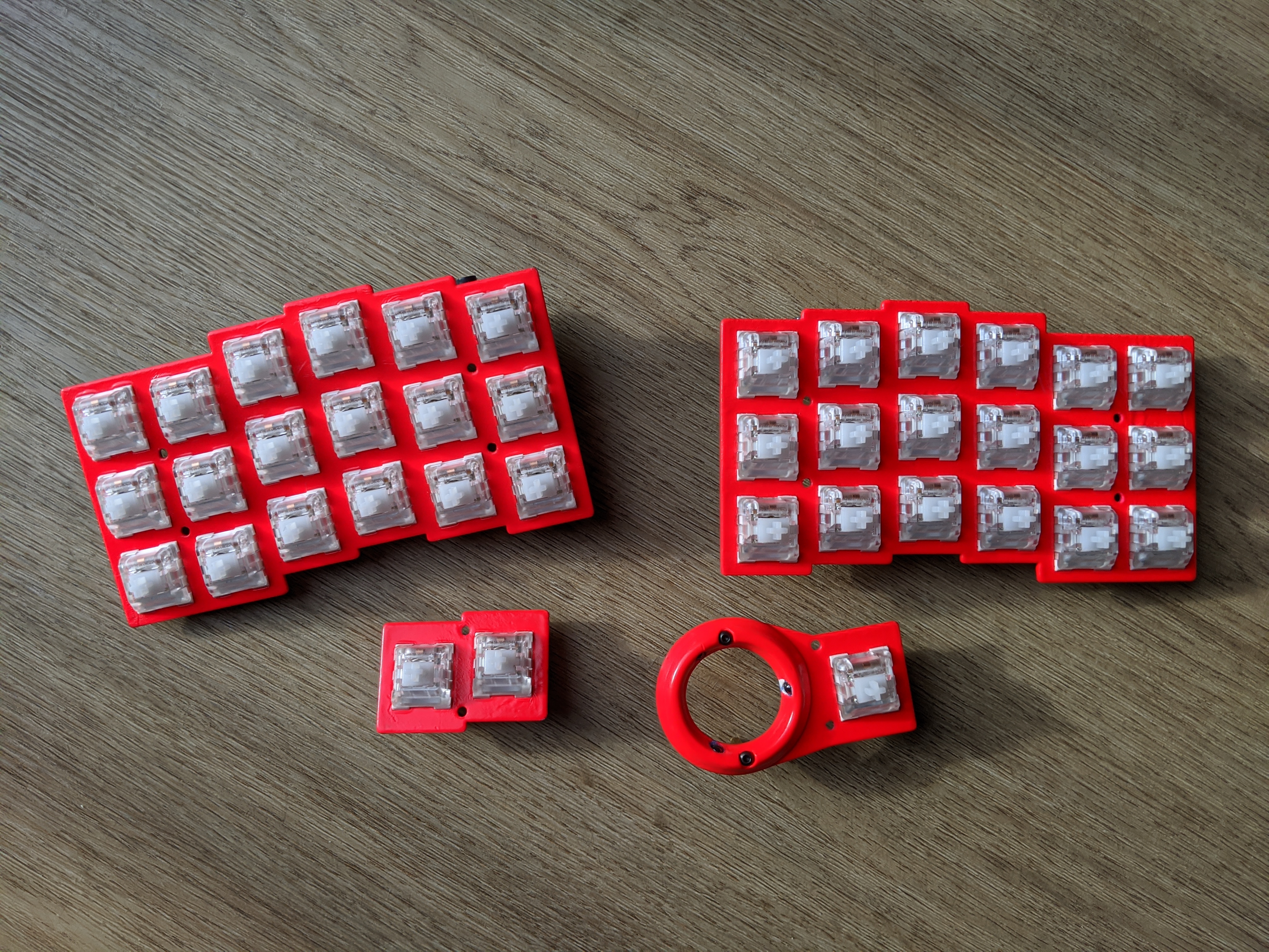
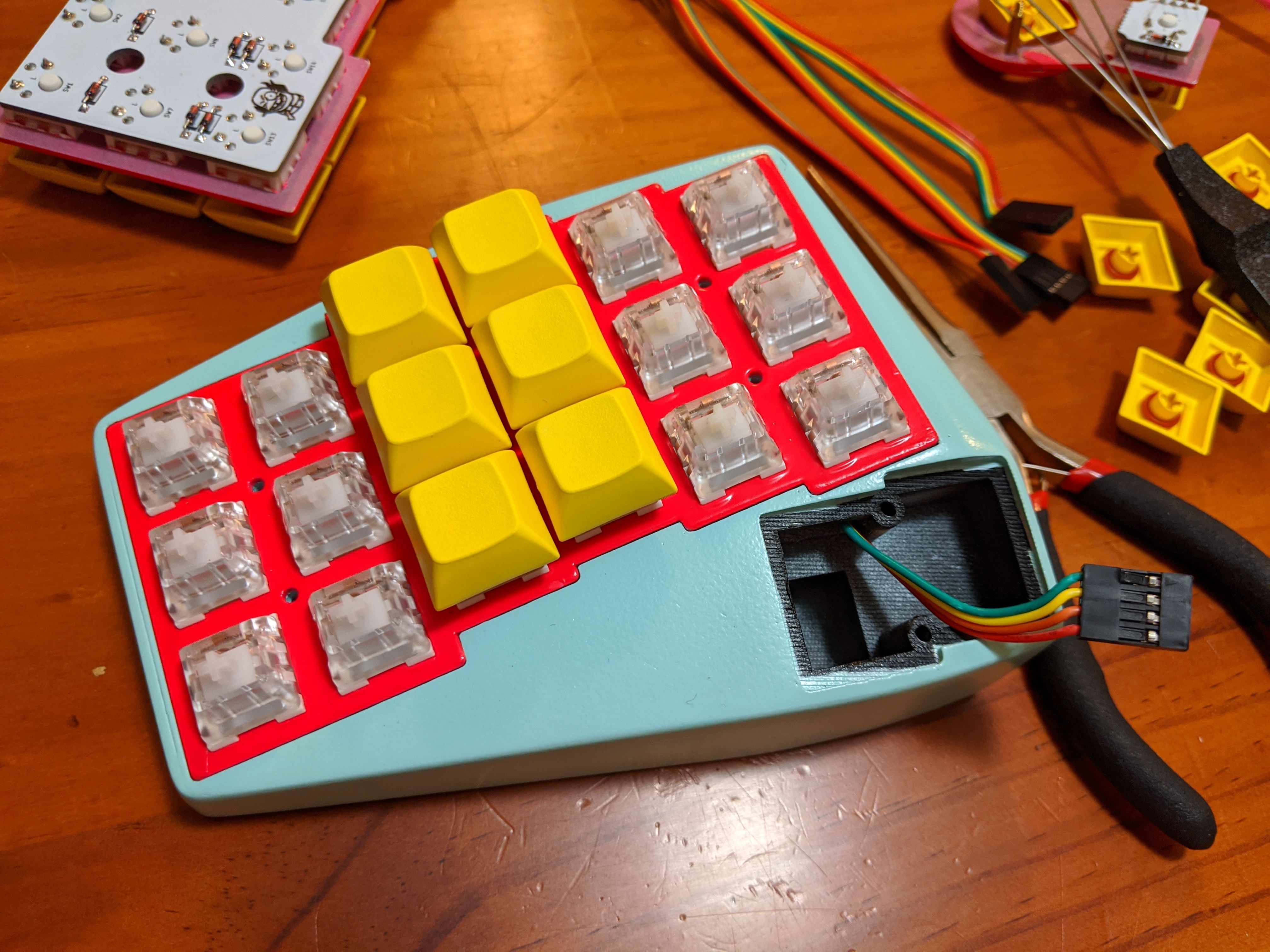
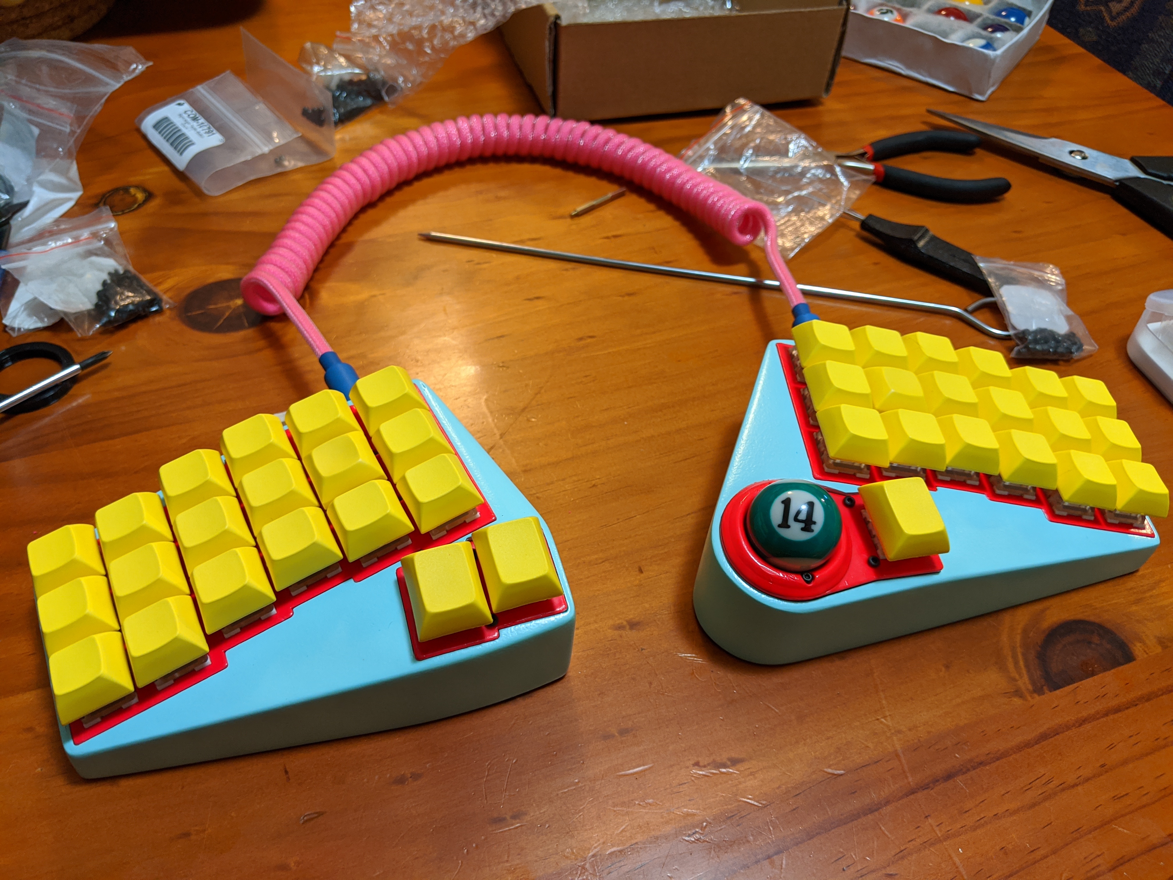
I was pretty happy with the result, and achieved all the main things I’d set out to from the start:
- split design
- just the right number of keys
- integrated trackball
- looks odd and cool
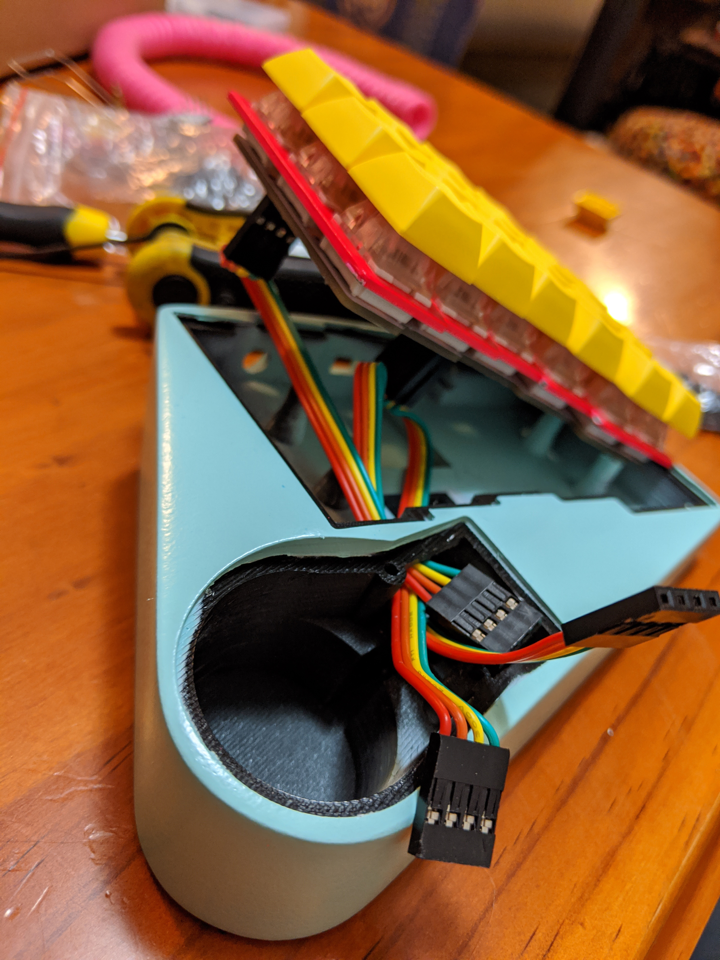
The main thing I’d change would be to move the trackball slightly closer to the right thumb. I moved the trackball quite far away as I thought I’d be flicking/spinning it all the time and didn’t want the 1.25u key to get in the way, however the thumb movements needed to move the trackball are much more subtle.
Between ebbing and flowing motivation, and waiting for deliveries, this whole process took me around 15 months. With that said, I really enjoyed the process! I learnt a lot: technically, using lots of software programs; getting used to 3D printing; learning the basics of electronics design and manufacture; practising waitng and being patient; and also a bit about how keyboards are constructed and the things that make them sound/feel/look the way they are. I’m quite relieved (and lucky) it all worked out in the end. I’d encourage anyone thinking of doing something similar to dive in; there are plenty of people and resources out there just waiting to help!